


Orange Unit: A Person-Centered Launch
2B: Electronic Components in Series
Background Knowledge Probe
Last session, we began to build our first electronic circuits. Along the way, we used videos, diagrams, and to inform and guide our work.
- How does this build on your everyday works in the communities of which you are a part? How does it contrast with your everyday works?
- How did you work with others on last session’s exercises, whether in person or remotely, synchronously or asynchronously, to achieve the immediate goal of physical making and the more general learning outcomes of the exercise and chapter?
- Going into this session’s exercises, what might you do similarly? What might you do differently so as to better achieve immediate goals and general learning outcomes?
Exercise: A Momentary Switch in Series with LEDs and Resistor
First, we’ll restructure the circuit of the three LED components in such a way that they run in series with a single resistor. Next, we will add a momentary push button electronic component. It is called a “switch” because it changes the flow of current depending on the state of the switch. It is called “momentary” because this change in state only occurs while a physical action is happening — in this case, the pressing of the button.

Before going through the steps, try watching the video:
Steps
You are highly encouraged to do this with one or two other people who are simultaneously working on their own toolkits. One person should do the work hands-on while the other(s) observe, work to identify yet/not yet moments, and do explorations to help facilitate failing forward. After the first person reaches a certain point as agreed upon by the collaborative, then the other(s) will work through those same steps with support from the first person. In this way, will be implemented.
- Remove the three resistors previously used with the LEDs from the breadboard. Leave the LEDs and jumper wires connected to the breadboard as is.
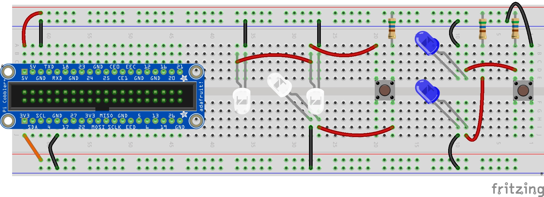
- Add in three new 6 inch jumper wires as specified in the diagram.
- Add back in one of the 560 Ω resistors into the location specified in the diagram.
- Optionally, use pliers to straighten the four legs on a momentary switch.
- Carefully insert the momentary switch into your breadboard in the specified pins from the diagram.
- Use “Yet/Not Yet” troubleshooting to determine if:
- The LED in columns 27 and 28, row H comes on after connecting the switch to the breadboard.
- The LED in columns 27 and 28, and the LED in columns 36 and 37, both in row B, come on after the push button is pressed down.
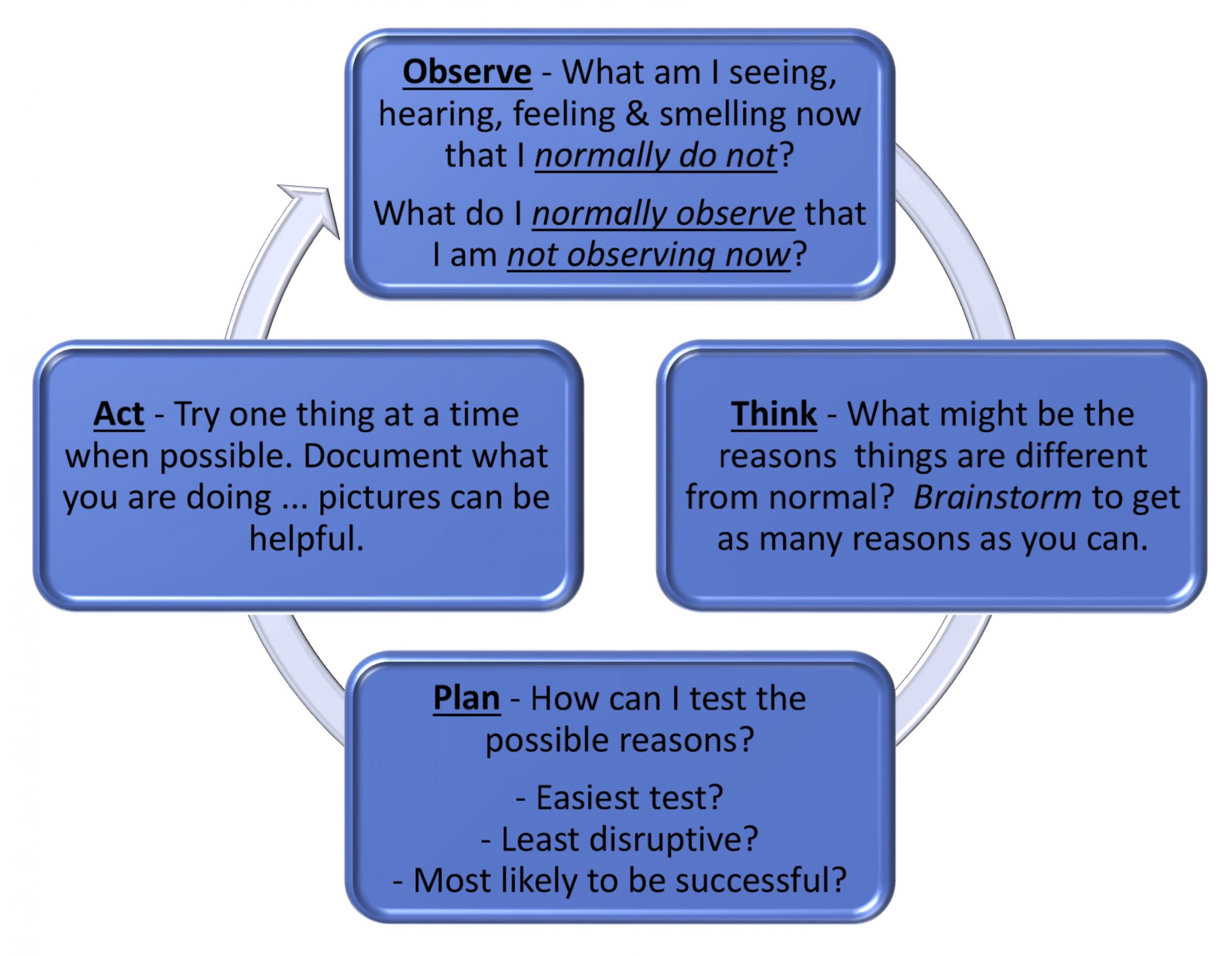
- If “Not Yet” for either check, proceed to fail forward using our troubleshooting strategies:
Key Takeaways
The flow of an electric through a circuit occurs in a predictable and controllable fashion and deductive reasoning serves exceptionally well in the exploration of these. As we saw in this exercise, no matter the physical change we make with the momentary switch push button, current always passes through the resistor and one leg of the momentary switch. Current then continues on to the lower LED on the breadboard before arriving at ground. The current will continue to flow through the circuit, as long as:
- The electrical components remain physically connected to the jumper wires and the metal conductors within the breadboard with sufficient magnitude.
- The five volts of power and ground remain connected to appropriate sources.
We also saw that when the push button is sufficiently pressed, current also flows to the other two legs of the switch. This incorporates the other two LEDs in series with the circuit.
We also compared the view of a circuit using schematics and diagrams, each seated next to the physical, constructed prototype. As we seek to demystify technology, we’ll continue to see how multiple points of view help to fill in gaps in our understanding of what is actually happening “beneath the hood,” and how we might implement it in our own works to shape its impact in our daily lives.
We’ve already discovered that if you increase the size of the resistor from 560 Ω to 10,000 Ω, the brightness of our 3mm white LED is reduced considerably. Indeed, the increased dims the LED more than a reduction in the of our electrical source from 5 volts to 3.3 volts.
When working with electrical , there is a proportional relationship between three measurements influencing the passage of an electrical charge:
- Electromotive force, listed in volts (e.g., 5V, 3.3V)
- Electrical resistance, listed in ohms (e.g., 560 ohms, 10K ohms)
- Electrical current, listed as amperes, or amps
Recall earlier, we tested the influence of different voltages and different ohms on the brightness of an LED. As we increase voltage, we also increase brightness. On the other hand, as we increase the ohms of resistance, we decrease brightness. This is because voltage increases current, while resistance decreases current.
And it is current that is used by an LED to make light. More current, more light.
A fourth measurement, watts, is a comprehensive measurement of power as influenced by the above three measurements. You may recognize the term watts in relation to lighting, as in a 60 watt incandescent light bulb. An equivalent LED light bulb, in brightness, would use about 8.5 watts of power. Our little white LEDs use closer to 75 milliwatts (mW) of power.
Like lights everywhere, they dissipate power in a predictable physical manner, such that at a certain point increasing the number of LEDs within a defined circuit decreases the brightness of those LEDs. It is for this reason that we see the dimming of all three LEDs when the momentary switch is pressed and current passes through to all three LEDs simultaneously.
As more components are added within an electrical circuit, the flow of current remains the same, to the extent that it is a closed loop between current and ground. Components work in series to direct, redirect, and influence the force and resistance of the current passing through this loop in a range of ways.
Exercise: From Circuits in Series to Circuits in Parallel with a Momentary Switch
In the last exercise, we created a circuit in which three LEDs ran in series. That is, the 5 volts passed through the single resistor, decreasing the current, and then passed through the momentary switch to one or to all three LEDs, depending on the state of the push button.
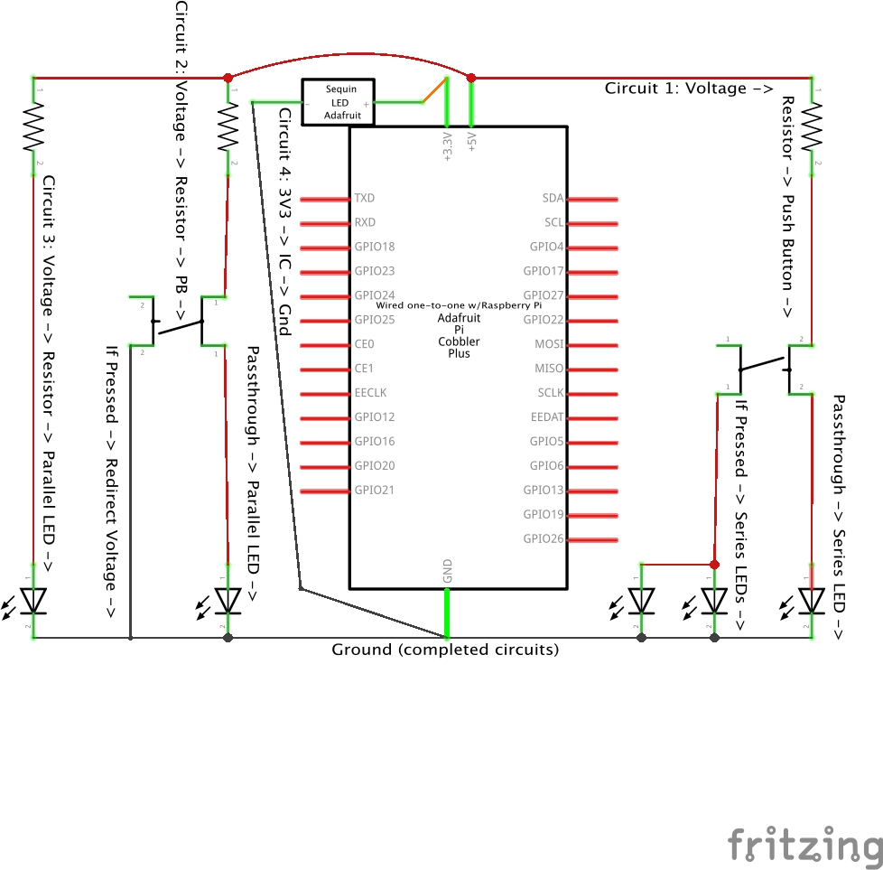
Let’s create two new circuits, each running in parallel to the first. This time, rather than watching a video demonstration first, try doing this as a pair or group of three using the Fritzing diagram as a starting point.[1]
Steps
- Review the breadboard diagram below to identify the columns of the breadboard used in testing.
- For fun, let’s try out two 10mm blue LEDs that came with the kit. For one, we’ll bring 5 volts to a 560 Ω resistor to the anode of the LED. We’ll connect the cathode of the LED to ground.
- For the other, though, we’ll connect one pair of legs of the switch to 5 volts, and the other pair of legs to ground. In this way, pressing down on the push button will switch the 5 volts directly to ground, completing the circuit. We’ll also connect the 5 volt legs of the switch to the anode leg of the other 10mm blue LED. We’ll connect the cathode leg of that blue LED to ground as well.
- With the above completed, compare the impacts on the LEDs of pressing the button on the two different circuits that incorporate switches.
- Further, compare how the pressing of the two switches impacts the brightness of the LED in a standalone circuit.

Key Takeaways
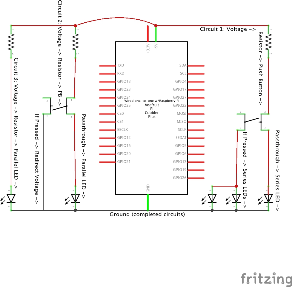
From the Raspberry Pi, 50 milliamps (mA) of current flow from the voltage pins of the , which we have connected to the red rail on the breadboard using a jumper wire. In this way, we can connect each circuit to the red rail, thereby passing that 50 mA to the rest of each circuit. If there is only one LED within the circuit, it has access to the total power passing through that circuit. On the other hand, when there are three LEDs in series on that circuit, each draws some of the power from that circuit.
Take a moment to review the schematic below to compare how each of the three circuits establishes a complete and closed path in which current can flow. Compare this to the diagram showing the conductors and components used to form this complete and closed path.
- How did this exercise compare to past exercises in which you were encouraged to watch a video demonstration first and then proceed forward in programming pairs?
- How might you have designed the setup of these circuits on the breadboard to better achieve that which you value doing? Why?
- In what ways are you reconfiguring the layout of the circuit schematic on the breadboard? In what ways are you designing a new circuit?
More on Transistors
Starting in the 1960s, a new term was heard in relation to radios, calculators, and televisions. I remember the commercial that inspired our family to get its first “transistor radio.” I also remember going to the Five and Dime or drug store to purchase a vacuum tube until we finally got that transistor television. replace those tubes by providing a having at least three legs: a source current terminal; a drain current terminal; and a gate terminal, which controls the output current.
- If the transistor gate is used to facilitate changes up and down in the voltage of the output, the transistor serves as an amplifier, something that can be used to control the volume of the transistor radio, for instance. As another example, consider the value of a transistor amplifier as LED dimmer!
- If the gate is used to control the “on/off” state of the circuit, the transistor serves as a switch. While our momentary switch circuits above required a physical act, the pushing of a button, a transistor switch uses an electrical input to determine the state of the circuit. Sometimes transistors do make use of some form of physical on/off switch or a momentary switch like the ones we’ve been using. At other times, the gate could use a microcontroller or microcomputer program to provide a digital on/off signal or analog low to high voltage signal.
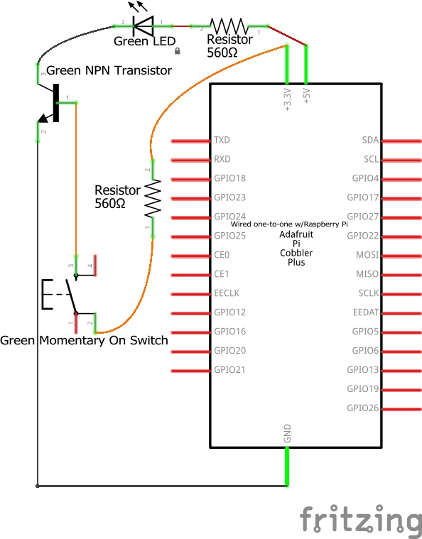
A transistor switch is more straightforward and therefore a better demonstration for our purposes. Here’s an example of a 5V → 560 Ω resistor → 10mm green LED → N-type, or NPN, transistor circuit, in which a 3.3V momentary switch is used to temporarily pass the current through the transistor to ground.
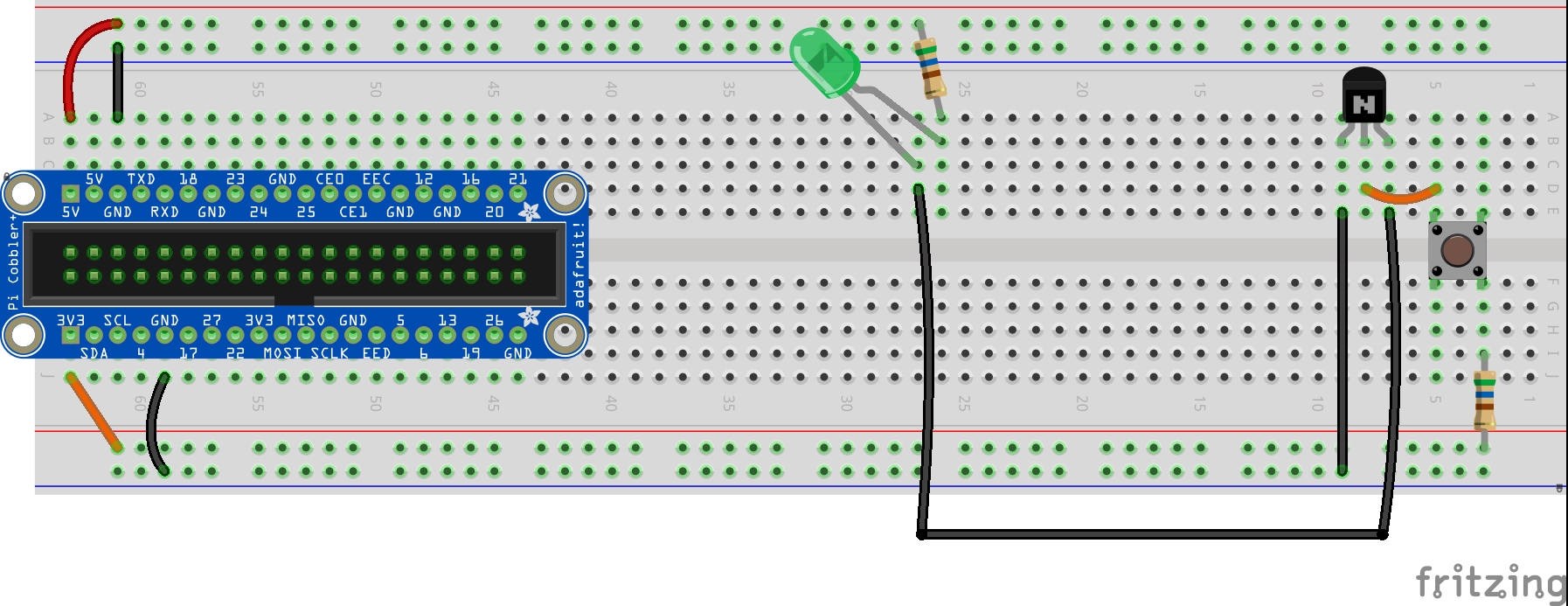
If you glance at the schematic, there’s an arrow symbol at the drain terminal (also sometimes called the “emitter”) of the transistor. The N-type transistor is off unless the gate (also sometimes called the “base”) receives a small current, thereby completing, that is, closing the currently open circuit by passing ground to the cathode LED of the leg.
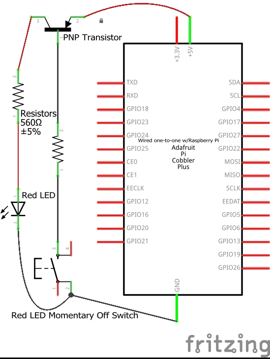
And here’s an example of a 5V → P-type, or PNP, transistor → 560 Ω resistor → 10mm red LED → GND circuit, in which the ground source also is sent through a momentary switch to another 560 Ω resistor to the PNP Transistor gate to temporarily turn on the current flow through the transistor, this time by temporarily grounding the base of the PNP transistor, creating a closed circuit by adding the current to the anode leg of the LED. 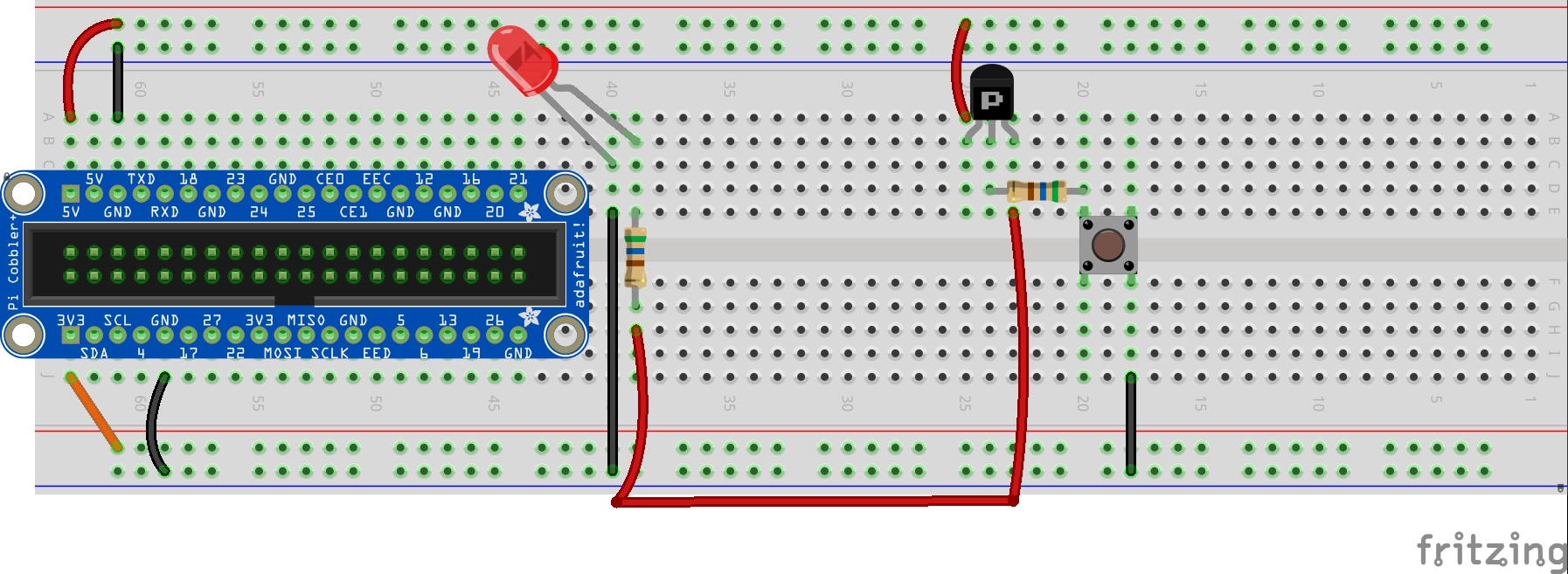
How might you add a NPN transistor remix into the Blue LED Circuit 2 above, the circuit in which the LED is continuously on unless the momentary switch is temporarily pressed?
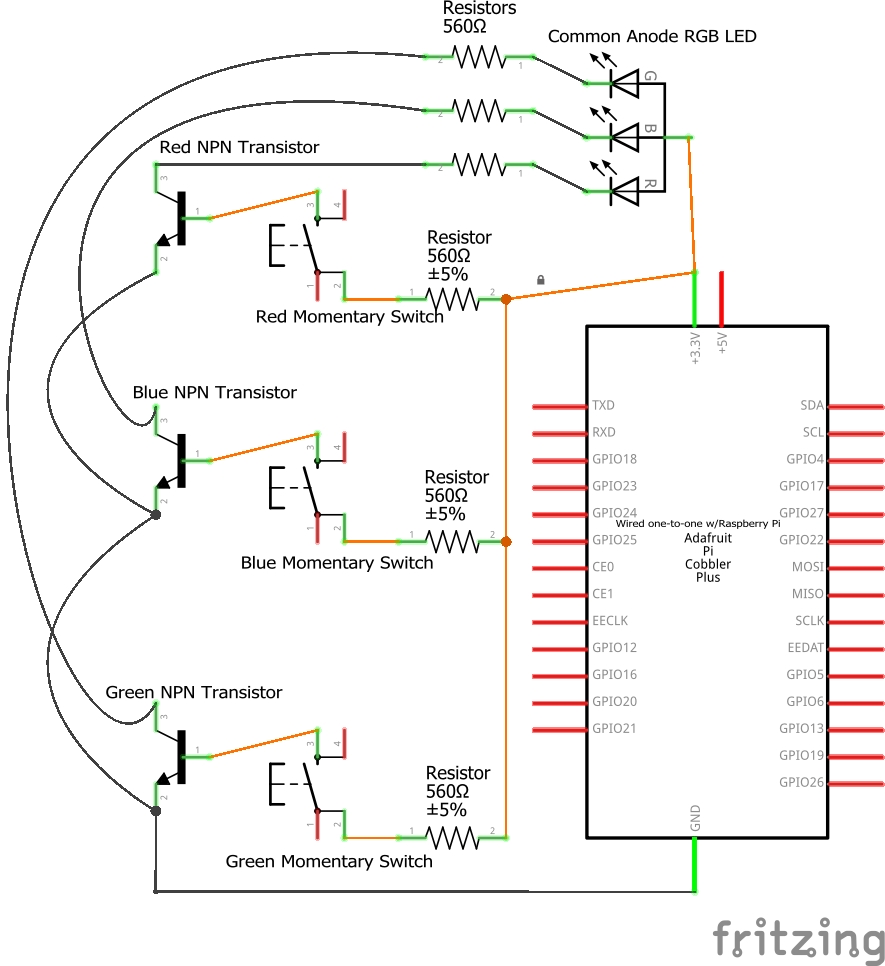
As one last example, let’s replace the individual LEDs with an RGB (Red, Green, Blue) LED. These are constructed of three different types of crystals, one to make red light, another to make a green light, and a third to make a blue light. Technically, with the right setup we could see a million different colors. But as our electronic components and breadboard are currently configured to provide set voltages of 3.3V or 5V, our rainbow of colors is a bit more limited. Here’s a demonstration of a circuit with three transistor and momentary on switch pairings to provide seven different colors from a switching RGB LED circuit:

Do Something New!
For some, your lived experiences have helped you quickly move through the above exercises and review the associated key takeaways. Perhaps you’ve even repaired or built your own electronic circuits previously. If so, now might be a great time to try an Innovation-in-Use of the circuits we’ve already built to do the exercises above in a new way based on your own design inspirations.
Or maybe you’ve noticed some of the other electronic components included in your toolkit or that you personally have on hand that we haven’t made use of through the exercises in the first two sessions, items that you think would serve to take the circuit prototypes to a new level. Feel encouraged to consider entering into a collaboration with others to Remix through rapid prototyping on your breadboards!
Exercise: From Breadboard Prototypes to Integrated Circuits
So far, we’ve placed individual electronic components on a breadboard to build a circuit. This is a very common way to rapidly prototype a product. In this way, we’ve been able to test different levels of resistance, models of LEDs, the number of LEDs in series, and whether or not to include a switch or amplifier within the product.
From here, the larger circuit built using discrete components is typically brought together onto a small piece of semiconductive material and then etched onto a flat insulating sheet called a printed circuit board. Semiconductors can bring together many individual resistor, capacitor, and diode components, such as the ones we’ve used above as part of our exercises. And they can include other semiconductors, such as the transistor semiconductor just described above. And our Circuit Playground Express kits come with five Adafruit-designed individual LED integrated circuits they call Sequins.
Next, let’s add an LED integrated circuit to the breadboard.

Steps
In pairs, have one run through this test while the other observes. Then swap roles. Provide support to each other throughout, and make use of the videos as a guide.
- Connect a black alligator clip to male jumper wire to the bottom blue rail of the breadboard. Connect a second alligator clip to male jumper wire (it can be any color of your choosing), to the bottom 3V3 red rail of the breadboard.
- Carefully identify the + and the – symbols on each of the five Sequins.
- Connect the black alligator clip (the one with the male jumper wire connected to the blue ground rail) to the – symbol on one of the five Sequins.
- Connect the other alligator clip (the one with the male jumper wire connection to the 3.3 volt rail) to the + symbol of the chosen, grounded Sequin.
- Carefully disconnect the 3.3 volt alligator clip from the Sequin to turn off the light, then disconnect the ground alligator clip from the Sequin. Then test the other four Sequins: connect the black ground alligator clip to a second Sequin, followed by the 3.3 volt alligator clip to that second Sequin. Repeat for the last two Sequins.
- NOTE: If one of the Sequin Integrated Circuits burns out, and I’ve done that a time or two myself, consider fail-forward strategies for the person working hands-on with the electronics to improve their probability of “Yes” in their next lighting of a Sequin.
Key Takeaways
Each Sequin is an integrated circuit comprised of a resistor and an LED. These are incorporated onto a printed circuit board along with conducting material, such that when voltage and ground sources are applied to the + and – strips, the LED is lit.
Take a few minutes to watch this video demonstrating the steps to connect the Sequin Integrated Circuit and reviewing these components compared to other integrated circuits and electronic tools which use those parts.
NOTE: For those interested, there’s a side video showing the behind-the-scenes soldering of the Perma-Proto Breadboard creation shown in the video above:
- In the above schematic, how does the circuit using the Sequin integrated circuit compare with the three previous circuits we have constructed?
- How does the Sequin compare to other integrated circuit components, like the one integrated into a remote door opener as seen in the video?
Wrap Up
This exploration of electronics lays the foundation for what we may want to design and create as part of our ongoing person-centered valued designs and builds. There are other electronics in the toolkit that we won’t work with directly, but that you might want to include in your own work. And there are many other electronics available for your consideration if you so choose. I highlight a few in this video:
Comprehension Check
- Fritzing breadboard graphics are licensed under CC-BY-SA 3.0. ↵
A symbolic and simplified diagram or other representation of a circuit. Throughout this book, schematics are used when an illustration of a circuit is needed without specifying exactly how these would be physically built using a breadboard or other prototyping platform. In this schematic illustration, we see the formal representation of the electronics used to create a complete and functioning circuit that include a 560 Ohm resistor, a 5mm LED circuit, and a battery. In the prototype illustration, we see one example of how this circuit could be constructed using a tiny breadboard and double-A battery.
A semiconductor that passes current from one terminal to another terminal, and in which current can only flow in one direction. The kit used in this book includes a mix of different Light Emitting Diodes, or LEDs. Different LEDs work at different wavelengths (the measure of distance between the peak and the trough in a wave), associated with different recognized colors of light. Some LEDs are made to be especially bright, such as a car headlamp to help us see the road more clearly. Others are meant to be more diffuse, thereby working more as a source of information, like a car brake light or turn signal.
Electrical switches are devices used to move between closed position, in which a current is passed through a circuit, and open position, in which the current is not passed through. A classic example is a light switch, in which a closed position would turn on a light and an open position would turn off that light. Closing the switch completes the circuit. The kit in this book includes three momentary closed tactile pushbutton switches that can be used with the breadboard, as well as three additional switches built into the Circuit Playground Express. Pressing on the round button momentarily closes the switch, temporarily passing current from one leg to the other on the switch. While the momentary switches used with the breadboard have four legs, the two legs on one side are connected together, as are the two legs on the other side. In practice, that makes these two-way switches.
Pair programming (or triplet programming) is common in software development. Two (or three) programmers collaborate on design, coding, and testing, with qualitative evidence suggesting the subsequent design is better, resulting in simpler code that is easier to extend. Further, whether the pair programming occurs between two novice programmers, between a novice programmer and a more experienced programmer, or between two experienced programmers, people learn significantly more about the system and about software development as both participants bring unique insights. Conversation between the programming pair can occur at many levels as the driver working at the keyboard takes charge of all changes made in the program and the navigator observes all the code that is entered, considers coding options, works to spot and address problems, considers and recommends simplifications, helps with programming style, and designs and verifies testing.
Current is a flow of electrons from relatively positive points to relatively negative points. Greater voltages have greater currents. As such, there is somewhat greater current when you use the 5 volt source of the Raspberry Pi than when you use the 3.3 volt source. Different electronics are capable of using different maximum currents, so it is sometimes necessary to provide resistance to reduce the current passing through the component.
Electrical resistance reduces the flow of current through a circuit. Resistors are the typical electrical component used to provide resistance in a circuit. The kit used in the book comes with five 560 ohm resistors, and five 10,000 ohm (or 10k ohm) resistors. In most cases, feel encouraged to work with the 560 Ω resistor.
A quantitative expression of the difference in charge between two points in an electrical field. The Raspberry Pi electronics kit provides both 5 volt and 3.3 volt sources for use in our circuits.
Electrical conductivity is the capacity to transmit electricity from one place to another. There are many different substances, such as copper wires and other bare metal pins, that are used to build electronic components. Examples of conductors include breadboards, jumper wires, printed circuit boards, and ribbon cables.
A general purpose input/output, or GPIO, is a common, open-ended transmission mechanism used with integrated circuits on microcontrollers, microcomputers, and other printed circuit board electronics. Pins are provided to which female-ended wires can be connected. GPIO pins can be programmed as input (e.g., sensor data; ground) or output (e.g., state change; power) sources. GPIO pins can be preconfigured for special purposes, or can remain undefined until specified by a user at run time. In general, GPIO provides a means to tailor pins to fit specific design goals within applications, as well as reusability across applications.
Small electronic switches allowing control of electrical flow within a circuit without using programming code.
A substance that can conduct electricity under some conditions, but not under others. Many electrical components are built using such semi-conductive materials, including diodes, sensors, and integrated circuits.
