


Orange Unit: A Person-Centered Launch
2B: Electronic Components in Series
Background Knowledge Probe
Last session, we began to build our first electronic circuits. Along the way, we used diagrams and schematics to inform and guide our work.
- How does this build on your everyday works in the communities of which you are a part? How does it contrast with your everyday works?
- How did you work with others on last session’s exercises, whether in person or remotely, synchronously or asynchronously, to achieve the immediate goal of physical making and the more general learning outcomes of the exercise and chapter?
- Going into this session’s exercises, what might you do similarly? What might you do differently so as to better achieve immediate goals and general learning outcomes?
- Unplugging one circuit from the breadboard—for instance, by disconnecting the voltage regulator used to switch 5-volt power to 3.3-volt power used by two for four bright white LEDs used in session one of the orange unit—does not disrupt the other parallel circuits on the breadboard.
- Unplugging something connected to a wall outlet will disrupt the flow of current to itself and everything else connected to it in series, as would be the case if we unplugged the USB to TTL cable from a wall outlet, which then removes the flow of current to all circuits on the breadboard.
- Unplugging something connected to one receptacle of a two-receptacle wall outlet does not disrupt the electrical device plugged into the other, as they are running in parallel to each other, as would be the case if two different USB to TTL cables were plugged in two different receptacles on one wall outlet.
- Unplugging something from this one wall outlet does not disrupt the flow of current passing along the electrical wiring connecting the other wall outlets in series with this branch circuit.
- Plugging something into one wall outlet that requires more amps than provided by this one branch circuit, or plugging in multiple electronic devices that together require more amps than provided by this one branch circuit, will likely trigger the breaker for this branch circuit, stopping the flow of current to everything on this series.[2]
- Disconnecting the electrical wires between one wall outlet and the next further down in the series does not disrupt the functioning of electrical devices running on this wall outlet, or the functioning of those before this one in the series.
- Turning off the branch circuit breaker in the main service panel turns off all wall outlets running in series from this branch circuit, along with all electrical devices plugged into these wall outlets.
- Turning off the main breaker in the main service panel turns off this and all other branch circuit breakers, which turns off all wall outlets, lights, and other electronic components running in series from each of the branch circuit breakers.
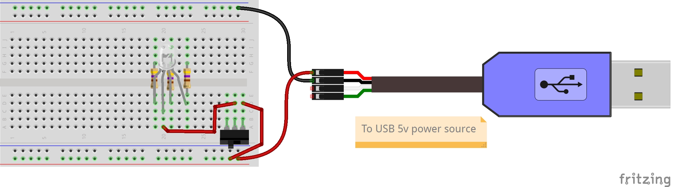
Looking specifically at our current breadboard configuration, the on/off slide switch is in series, with the USB to TTL cable on the upstream side and the anode leg of the RGB LED on the other. Unplugging the USB to TTL cable breaks the flow of current for all devices on the breadboard. Sliding the switch from on to off breaks the flow of current to the anode leg of the RGB LED. But beyond the anode leg, the three LED chips of the RGB LED work in parallel. Failure of one LED chip does not necessarily mean the other two LED chips will fail, depending on cause of failure. As we discovered in the first activity of Orange Unit 1B, we could plug only one of the three chips into the blue ground rail, and it would work even as the other two did not because of their lack of a ground connection completing that circuit. If the resistor for one failed, the other two parallel circuits would continue to work.
Consider strings of holiday lights, along with other lights plugged into the wall outlets of a circuit. Modern holiday lights will continue to work even if one light within the string fails—each light is its own parallel circuit on the string. But in some cases, there may be two separate series of lights, so that if one series reaches an open state, only half the lights stop working. The second, parallel series of lights remain in a closed state. Also consider that the lights plugged into one wall outlet do not impact the lights plugged into other outlets, unless together the number of lights all plugged in require more amps than can be provided by this branch circuit of wall outlets running in series. The different lights are working in parallel to each other.
Exercise: Momentary Switch RGB LEDs in Series
In this activity, we will add three momentary switch push button electronic components. As with the slide switch we added in the first unit, the push button is called a “switch” because it changes the flow of current depending on the state of the switch. These push buttons are called “momentary” switches because this change in state only occurs while a physical action is happening—in this case, the pressing of the button. Each switch is connected in series with one of the RGB LED cathode legs that themselves are running in parallel to each other.
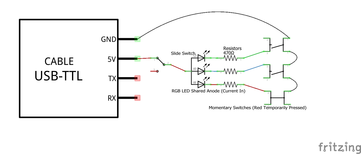
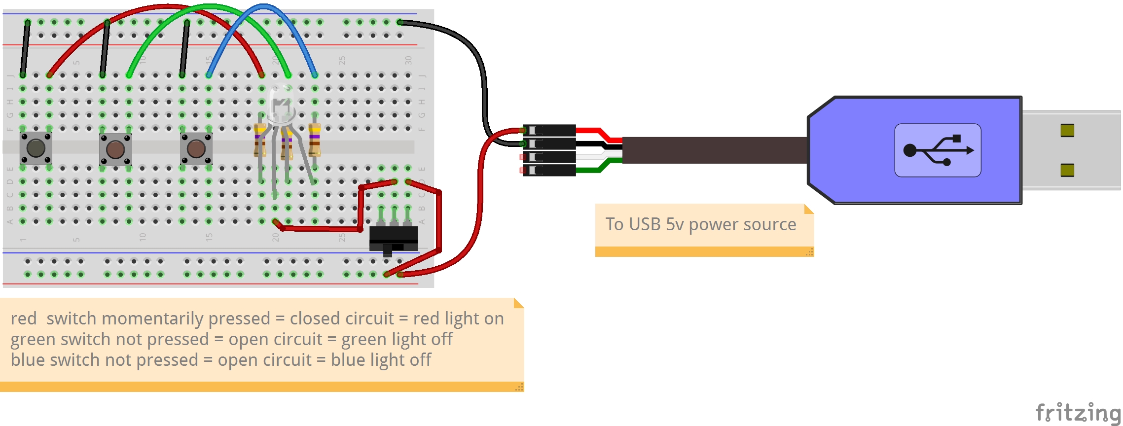
In the Fritzing[3] schematic above, the momentary switch push button symbols for the green and blue cathode legs of the RGB LED are in their default state, and so they are not connected to ground and are open circuits. As the circuits are incomplete, the green and blue cathode legs are “off,” just as they are when the slide switch slides to the left, or off, pin, and do not receive current at the beginning of the circuit cycle. The momentary switch push button symbol for the red cathode leg, on the other hand, is in the momentary pressed position. As a result, there is a line connecting the cathode leg and 470 ohm resistor to the rest of the cycle moving to ground. In this schematic, the slide switch symbol also indicates it is in the “on” position to provide 5V power to the common anode leg, so the red LED circuit is temporarily a closed circuit, and the red LED is lit!
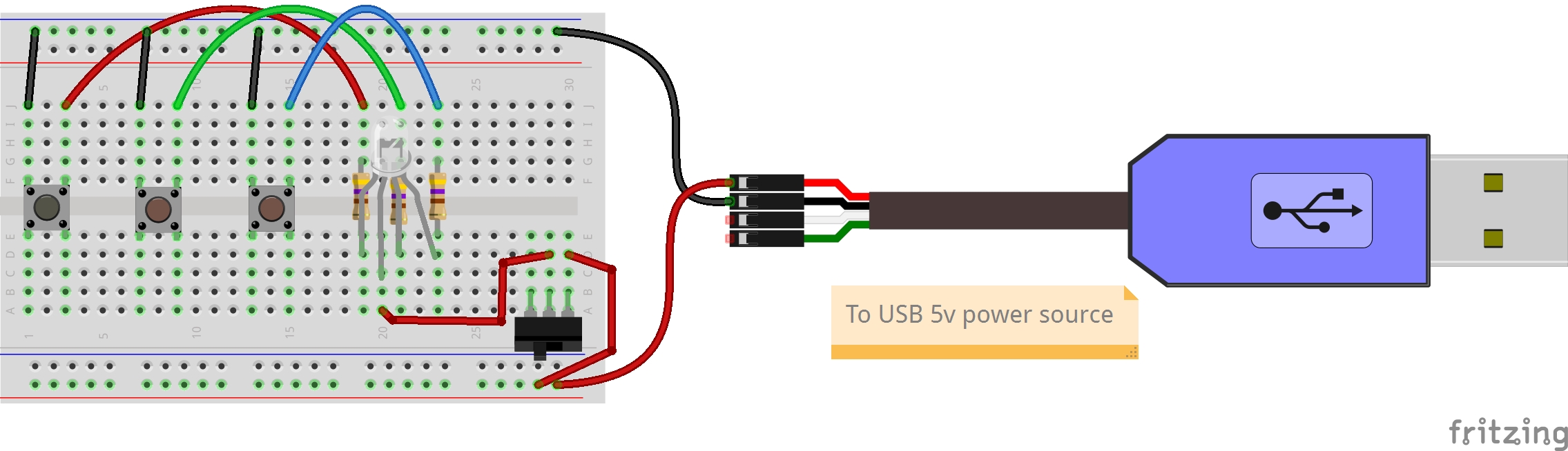
This is represented in the diagram below, with two brown momentary switch push buttons for the green and blue cathode legs of the RGB LED, and a black momentary switch push button for the red cathode leg of the RGB LED.
Each of the momentary switch push buttons has four legs, paired such that two on each side bend slightly out and then back in. Each pair is designed to sit above or below the center line, delineating A-E from F-J of a column. Each pair consists of a side 1 and a side 2 of the switch as labeled within the schematic, in which the sides are by default disconnected and are only momentarily connected when the button is pushed down. In so doing, the flow of current is passed through the switch.
Steps
- Disconnect the male/male connecting the red, green, and blue cathode legs of the RGB LED to the upper blue rail of the breadboard.

- Straighten the four legs of the momentary switch.
- The design of the legs for the switches is primarily for a permaproto board, a breadboard that requires connections be joined together by putting a melted filler metal into the joints.
- That said, the legs of the switch can also work in our breadboards where there the conductive ends of wires and electronic components are slid into the metal filler.
- To improve these, use a flathead screwdriver or some pliers to straighten each of the four legs on each of the switches.
- Connect one switch to columns 1 and 3. Connect a second switch to columns 7 and 9. Connect a third switch to columns 12 and 15.
- Using three male/male jumper wires, connect row J of columns 3, 7, and 11 to the upper blue rail of the breadboard as shown in the diagram.
- Using three more male/male jumper wires, connect row J of columns 5, 9, and 13 to row J of columns 26, 28, and 30. In so doing, you now have set up three switched circuits for the red, green, and blue cathode legs of the RGB LED!
- This may prove a “not yet” moment for one or more of these circuits.
Bring together pair programming and our troubleshooting strategies to fail forward for any breadboards that are not yet working on your pod. Be sure not to have those who have reached a state of “yet” fix the problem for others, but rather provide extra eyes on the instructions and troubleshooting strategies list to work collaboratively on the problem. In so doing, all have the potential for social and technical learning beyond what either partner might do individually.

Key Takeaways
The flow of an electric current through a occurs in a predictable and controllable fashion, and deductive reasoning serves exceptionally well in the exploration of that which is predictable and controllable. As we saw in this exercise, no matter the physical change we make with the momentary switch push button, current always passes through the resistor and through one leg of the momentary switch. The momentary switch plays a make-or-break role. For our momentary switch, while the button is unpressed, it is in a break state, and the circuit does not reach ground to complete the circuit. It is an open circuit. We also saw that when the push button is sufficiently pressed to reach a make state, current flows to the other leg of the switch. Only in returning the current to ground does it move from an open to a closed state. It is a now a closed circuit. In the above Fritzing image, the black dot in the center of the red momentary switch is used to indicate a pressed button, while the brown dots of the green and blue momentary switches are used to indicate buttons that are not pressed.
We’ve now seen several of the many forms in which come. In this exercise, the slide switch and momentary switch push buttons are mechanically moved between the make state and the break state. In this aspect, they are like the mechanical breaker switch of a building’s main electrical panel and the multiple branch circuit breakers within the main panel which was explored to introduce this chapter. As with the slide switch, breakers can be physically moved from the make, or ON, side, to the break, or OFF, side. For building electrical, though, these breaker switches also have additional components to electrically trigger mechanical movement of these under certain circumstances, such as when electronic devices are pulling more amperage than is allowed by the breakers.
This exercise also compared the view of a circuit using and diagrams which could be viewed simultaneously with the physical, constructed breadboard prototype. As we seek to demystify technology, we’ll continue to see how multiple points of view help to fill in gaps in our understanding of what is actually happening “beneath the hood,” and how we might implement it in our own works to shape its impact in our daily lives.
Exercise: Adding LED Sequins in Series and in Parallel
In the first session of the Orange Unit, we discovered that if you increase the size of the resistor from 470 Ω to 10,000 Ω, the brightness of an is reduced considerably. Indeed, the increased resistance dims the LED more than a reduction in the voltage of our electrical source from 5 volts to 3.3 volts.
When working with electrical conductors, there is a proportional relationship between three measurements influencing the passage of an electrical charge:
- Electromotive , listed in volts (e.g., 5V, 3.3V)
- Electrical , listed in ohms (e.g., 560 ohms, 10K ohms)
- Electrical , listed as amperes, or amps
The influence of different voltages and different ohms on the brightness of an LED was tested in several ways to demonstrate that as we increase voltage, we also increase brightness. On the other hand, as we increase the ohms of resistance, we decrease brightness. This is because voltage increases current, while resistance decreases current.
And it is current that is used by an LED to make light. More current, more light.
A fourth measurement, , is a comprehensive measurement of power as influenced by the above three measurements. You may recognize the term “watts” in relation to lighting, as in a 60-watt incandescent light bulb. An equivalent-brightness LED light bulb would use about 8.5 watts of power. Our 10-millimeter diffused RGB LED is rated at 150 milliwatts (mW) of power at maximum.
Like lights everywhere, they dissipate power in a predictable physical manner, such that at a certain point, increasing the number of LEDs within a defined circuit decreases the brightness of those LEDs.
In this exercise, we will temporarily add two LED Sequins into the mix. Each Sequin is an comprised of a and an LED. These are incorporated onto a printed circuit board along with conducting material, such that when voltage and ground sources are applied to the + and – strips, the LED is lit. If you pick one of these up, you’ll notice they look and feel like some sort of flat plastic or other material. That’s the feel of a typical printed circuit board (PCB) used as the base for each of the microcontrollers and microcomputers we make use of daily.
For this activity, we’ll add one LED Sequin integrated circuit in series with the red cathode leg of the RGB LED. Breaking the slide switch, LED, or momentary switch connections in any way breaks the circuit for all items working in the series. We’ll add a second LED Sequin integrated circuit that will work in parallel to the other LED Sequin. As it is connected directly to its own 5-volt and ground rails, it will remain a closed circuit as long as power is provided to the breadboard. Together, these will allow us to further test the relationship of electronic components within a series and in relation to those of other electronic components in other, parallel circuits.
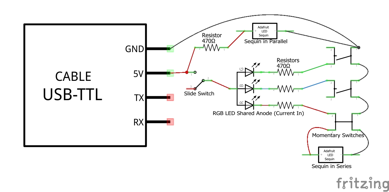
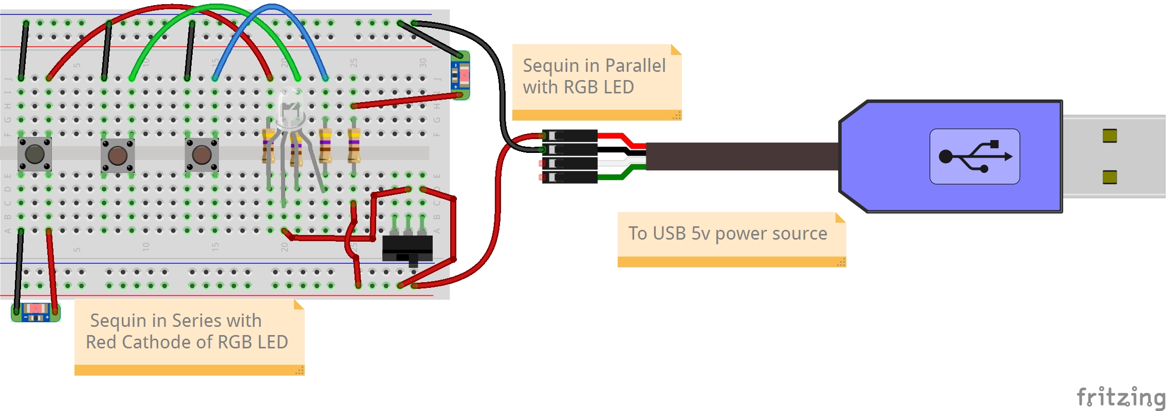
Note within the schematic that we have four parallel LED circuits:
- A red parallel LED circuit in series with an LED Sequin, a resistor, and a momentary switch, all with a single lead to ground.
- A blue parallel LED circuit in series with its own resistor and momentary switch with a separate lead to ground.
- A green parallel LED circuit in series with its own resistor and momentary switch with a third separate lead to ground.
- A second parallel LED circuit with its own resistor and a fourth separate lead to ground.
Steps
- Attach a male/alligator clip jumper wire from row A of column 3 to the + side of the sequin.
- Attach a male/alligator clip jumper wire from row A of column 1 to the – side of the sequin.
- Press the “red” momentary switch to confirm that both the Red RGB LED and Sequin LED series now light up when pressed.
- Attach a 470 Ω resistor in column 25 to bring together rows A-E and F-J.
- Connect a male/male jumper wire from the red 5V rail at the bottom to any available hole in rows A-E of column 25.
- Connect a male/alligator clip jumper wire in any available hole in rows F-J of column 25 and to the + side of the sequin.
- Connect a male/alligator clip jumper wire to the top blue ground rail and to the – side of the sequin. This sequin should remain on, independent of the condition of any of the other LED circuits.
There are now four parallel LED circuits with different light colors, brightnesses, and conditions in which they move from off to on and back.
Key Takeaways
There is a key distinction between that are running in versus those running in . If there are s in parallel, there are multiple paths can flow from source to ground. If the LEDs are in series, there is only one path from source, through the LEDs, and back to . Look again at the for this exercise:
Trace the route from 5V to GND for the Sequin in parallel. The current flows from a 5V power source through a and into the plus (+) side of the Sequin. It then leaves the negative (-) side of the Sequin before passing to GND. At the same time, the schematic makes note that as ground is reached through the blue rail of the , it completes the flow of the circuit down the same path as the other circuits. But this Sequin is doing it in parallel to the circuits of the other LEDs.
Now trace the path of the Sequin in series. The current leaves the 5V and passes through the slide switch, which if “on” sends the flow of current to the common leg of the RGB LED. Here it takes the path leading it to the red leg of the LED and passes through the resistor before entering one leg of the momentary switch. If this switch is pushed down, both the Sequin and the “red” RGB LED pass through an opposite leg of the momentary switch and return to ground. These LEDs are running in series to each other. There is only one path for both to progress from 5V to GND.
Circuits in parallel and series each have their pluses and minuses. The Sequin in parallel is not controlled by the slide switch and so has a constant brightness compared to the Sequin that passes through the slide switch and can be switched on or off. This is an advantage if you want an LED with constant brightness to give you an indication of something being plugged into a wall outlet or being active. It is a negative if you want to be able to turn off a light even though it still has 5-volt power available.
Of importance, note that we also find the amount of electricity used in the parallel LED circuit is double that used for the LEDs in series. There is a higher power consumption that would drain a battery faster or would require more power sent to the building from the electrical grid. While minute in overall terms, this is an important consideration when working to reduce overall power consumption.
When LEDs run in parallel, they each get one hundred percent of the current passing through the circuit. When LEDs run in series, they share a percentage of the current—in this example, fifty percent each. Since brightness depends on the amount of current passing through, the parallel Sequin will be brighter than the series Sequin. You’ll also note the brightness of the red RGB LED dims as well. Each of the three cathode legs of the RGB LED are running in parallel as they each follow a unique path back to ground. If each of these also had their own Sequin running in series, the cost in brightness might be offset by only using the 5V power option, by decreasing the resistor from 470 ohms, or a combination of the two.
As we see with hanging lights, those connected in series mean that a break at one point breaks everything within that series as the flow of current is switched from closed to open. Lights in parallel allow for one LED to break while others continue to work.
As we see from this example, there is often no clear and consistent answer as to which is the better circuit. And it’s here that strategic design joined with rapid prototyping and testing across diverse communities of users can help arrive at a better answer. Best does not exist, as we can never fully know the contexts for each user. Nor can we fully anticipate (or sometimes even make a rough guess regarding) the changes in context for a given user. As we move forward in this book, the takeaways here will hopefully help as we delve ever deeper into the sociotechnical devices and systems from which we select, and which we use and help others to use as part of our daily lives.
Do Something New!
We’ll come back to the RGB LED circuitry on the breadboard in session 4 of the Orange Unit, where we’ll use the right half of the breadboard to make connections with the Raspberry Pi general purpose input and output pins. This way, we can use Python programming code to read momentary switch inputs and open and close the RGB LED circuits. Then, at the start of the Rainbow Unit, we’ll bring together the programmable RGB LED circuitry of the Orange Unit with the programmable Toolbox Trumpet microcontroller we’ll use in the Blue Unit to create a demonstration model that could potentially be used to make your own Internet of Things device.
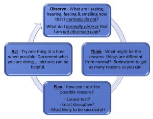
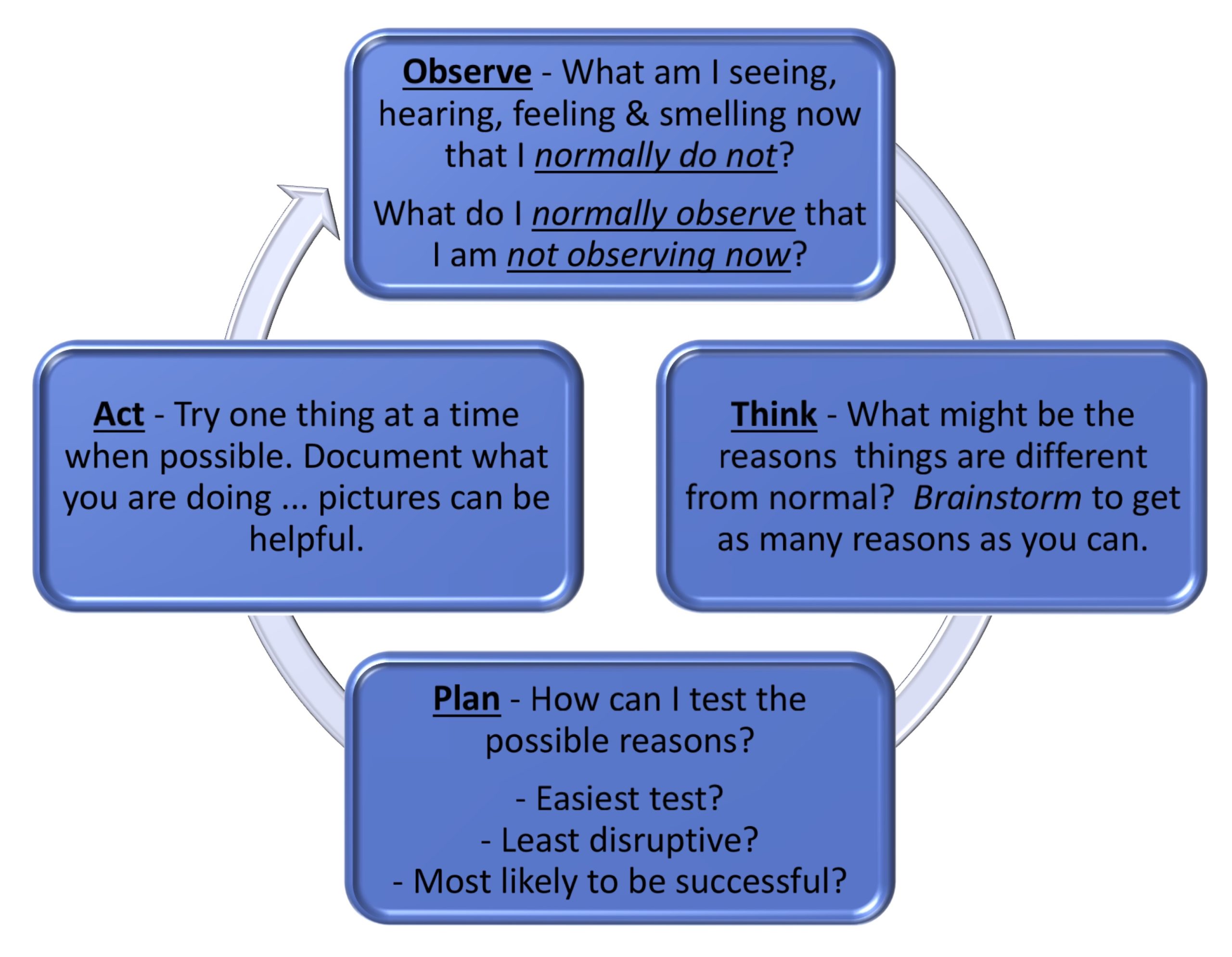
As we’ve worked through the exercises in sessions one and two of the Orange Unit, one key takeaway has been to encourage consideration of how demystifying technology requires risk-taking that brings us to moments of failure. As we observe these “not-yet” occurrences, think through possible social as well as technical factors shaping these occurrences, develop a plan for testing, and then act one step at a time upon this plan, we see in new ways what is underneath the hood of electronics. We begin unpacking how it is shaped by others. We start seeing how failure is sometimes as much a mismatch between the shaper and the user of the device as it is our failing. And we start thinking more deeply about how we can work to either align ourselves with the shapers of the technology or find ways to further shape the technology ourselves to better align with our ways of using it. To do this, we also are unpacking the importance of reflecting on our various creative actions and making written or spoken recordings of those actions and reflections. Failing forward can be a mix of changing our way of doing something and of changing how that something gets done.
In reflecting back on your actions and reflections of sessions one and two, have there been some moments when you found a mismatch between my shaping of the circuit’s design and your use of that circuit? Have you had a flash of inspiration regarding a better way to do the layout of the circuit to perhaps make it more usable for you?
Here’s an opportunity to Try Something New! using the breadboard, wires, and electronics as the rapid prototyping tool they’re intended to be. Consider testing out your idea(s) by rebuilding the switched power for the common anode of the RGB LED; the red, green, and blue momentary switched circuits; and/or the sequin LED circuits using columns 1-30 of the breadboard. Perfection is not on the table; bravery is!
Wrap Up
This exploration of electronics lays the foundation for what we may want to design and create as part of our ongoing person-centered valued designs and builds. You can likely find many other electronics in tinker- and makerspaces around you, which you could use to further dig into the many components used in the electronics of which you make daily use. Demystifying technology in this way can sometimes be an essential act helping you to see some of the situations limiting you or others from being and doing what you most value. This requires us to move beyond technical skills development, though, to include additional skills that help us to continually probe the mutual shaping and amplification of sociotechnical devices that has happened and is happening within this moment. As we work to problematize these sociotechnical artifacts, we also have the potential for advancing a more person-centered approach within our personal and professional lives.
Comprehension Check
- This is a simple example for descriptive purposes. In practice, one outlet might be the only one on a branch circuit, as is done for high-demand devices like an electrical stove and rangetop cooking combination or a large refrigerator. Or the wall outlet might branch to two other wall outlets creating two branch series circuits. ↵
- Within the United States context, general-purpose wall outlets typically provide 120 volts at 15- or 20-amps. ↵
- Fritzing breadboard graphics are licensed under CC-BY-SA 3.0. ↵
Wires are made of either a thicker solid metal or thinner strands of multiple wires, placed within a non-conductive material. The exposed ends of the wire can then be inserted into two different holes on the breadboard to safely conduct current from one hole to another, helping to extend the circuit between different electrical components. These are sometimes attached to a plastic holder to provide greater strength. If a solid metal wire end has been soldered into the other side of that plastic holder, it is known as a male end. If a metal wire can be temporarily inserted into the other side of that plastic holder, it is known as a female end. If a pair of metal clips attached with springs is provided, it is known as an alligator clip.
When working with electrical components, a circuit is the complete path that allows an electric current to flow from source voltage back to the source ground. Circuits generally include one or more electrical components along this path which are powered by the source.
A closed circuit is one in which current can flow fully from its source voltage to its ground return uninterrupted.
An open circuit is one in which there is an interruption in the flow of current from its source voltage to its ground return.
Electronic switches are used to control the flow of current on a circuit. They can be used to switch between the closed position, in which a current continues its flow through a circuit, and the open position, in which the current is not passed through. A classic example of this type is a light switch, in which a closed position would turn on a light and an open position would turn off that light. Closing the switch completes the circuit. Other switches are used to control the amount of current that flows across the circuit. A classic example of this type is a dimmer switch for a light used to brighten or dim the brightness of a light.
While the above are common mechanical switches, it is also possible to use programming code to switch the flow of current along a circuit. A common method for doing this is through use of a transistor, which uses a low current signal to one leg of the transistor provided by the program to determine the flow of a larger amount of current through the transistors other two legs.
A symbolic and simplified diagram or other representation of a circuit. Throughout this book, schematics are used when an illustration of a circuit is needed without specifying exactly how these would be physically built using a breadboard or other prototyping platform. In this schematic illustration, we see the formal representation of the electronics used to create a complete and functioning circuit that include a 560 ohm resistor, a 5mm LED circuit, and a battery. In the prototype illustration, we see one example of how this circuit could be constructed using a tiny breadboard and a double-A battery.
A semiconductor that passes current from one terminal to another terminal and in which current can only flow in one direction, known as rectification. Some common uses of diodes include reverse current protection, to clip or clamp circuits, and to provide logic gates. Another common usage is as a source for generating light, known as a Light-Emitting Diode, or LED. Different LEDs work at different wavelengths (the measure of distance between the peak and the trough in a wave), associated with different recognized colors of light. Some LEDs are made to be especially bright, such as a car headlamp made to help us see the road more clearly. Others are meant to be more diffuse, thereby working more as a source of information, like a car brake light or turn signal. Multiple light-emitting diodes can be packaged together in groups of three that include a red, a green, and a blue LED. These RGB LEDs can be further packaged together to create a full LED matrix display.
Voltage is a quantitative expression of the electromotive force required for a charge to pass between two points in an electrical field. Common household voltages include 120- and 240-volt circuits. Common computer and other microelectronic voltages include 12-, 5-, and 3.3-volt circuits. Electrical components are designed for specific voltages and need power adapters if the supply of energy does not meet the component requirements.
Electrical resistance reduces the flow of current through a circuit. Resistors are the typical electrical components used to provide resistance in a circuit, and are listed in ohms. For instance, the exercises in the book mainly use 470- or 560-ohm resistors, also abbreviated as 470 Ω or 560 Ω resistors.
Current is a flow of electrons from relatively positive points to relatively negative points, and is listed in amperes, or amps. Different electronics are capable of using different maximum currents, so it is sometimes necessary to provide resistance to reduce the current passing through the component.
A unit of power used to quantify the rate of energy transfer.
Integrated circuits (ICs) are semiconductor wafers which contain a collection of tiny resistors, capacitors, and transistors. These can then be built to serve a wide range of electronic functions. In practice, larger-sized electronic components used to build circuits are first tested using materials like breadboards for rapid prototyping. They are then redesigned to be built into integrated circuits and optimized for regular, more standardized use. At times, a mix of electronic components along with integrated circuits are themselves used on breadboards to do further rapid prototyping of yet larger circuitry. The 5-Key Capacitive Touch Sensor included in the kit for this book contains a mix of integrated circuits. Examples of integrated circuits include processors, memory, and controllers.
A complete, closed circuit in which current divides into multiple paths to ground. A failure on one path does not impact electronic components passing along another path running in parallel.
A complete, closed circuit in which there is one path along which current flows. When one electronic component along the path fails or is interrupted in some way, all components enter an open state and stop working.
In electrical engineering, ground, also called earth, provides a physical reference point in an electrical circuit from which voltage can be measured.
For electronic circuits, electrical ground, also called common, is the return path to a power supply.
Today, most building 120- and 240-volt outlets have power, common, and ground. Many microelectronics make use of only power and common, while certain of our electronics also need earth-source ground in addition to power and common, or electrical ground.
A breadboard used to be a board (sometimes literally a board for cutting bread) with nails pounded into it so that you could wrap wires around them to make experimental models of electric circuits. Today, the breadboard is a piece of plastic with holes in it. Underneath each hole is a metal clip. These metal clips connect together a specified set of holes ordered into a row or column. This way, pushing a piece of conductive material into one hole right away connects that material to things pushed into other holes that are joined together by that clip.
A perfboard is a thin, rigid sheet with holes but no metal clips on the other side. Instead, copper pads are used, to which conductors can be soldered. In some cases, as with the perma-proto breadboards from Adafruit, copper is further used to group together certain holes, mimicking the breadboard in a way that provides greater durability for prototyping work.
The positively charged electrodes conducting electric current from a cell into a device like a diode.
The negatively charged electrodes conducting electric current out of a device, like a diode, and back to a cell.
