


Orange Unit: A Person-Centered Launch
1B: Introduction to Electronic Circuits
Background Knowledge Probe
Write a list of the electronics that you make use of on a regular basis.
- Who comes to mind as the designers of these?
- What parts, inside and outside the hood, were used to build each one? To use it?
- What have you done with any items that started to work less than optimally?
Technical Introduction
Example: A Single LED Circuit
An electrical is a path in which electrons flow from source to ground. The source is usually measured in (the force, expressed in volts) or (the flow, expressed in amps). A (expressed in ohms) controls the flow of this source.
When I water my garden from a rain barrel, a full barrel has more pressure than one that is almost empty. That full barrel is the equivalent of a higher voltage , for instance, one that is 240 volts. A barrel two-thirds of the way full may be more like a 120 volt power source, while a nearly empty rain barrel may be closer to a 5 volt power source.
If I have a spray nozzle hooked up to my rain barrel, I can often use a lever to increase or decrease the water’s flow. This is equivalent to the current of the power source. Some of my water hoses are 1/2″ thick, while some are 3/4″ thick. This is equivalent to bigger or smaller ohms of a resistor, respectively, since a thinner hose increases the resistance of the flow of water compared to the thicker hose.
As a side note, in electrical engineering, provides a basic equation I=V/R. This states that current (I) is equal to voltage (V) divided by resistance (R). And as all Trekkies know from their days with Jean-Luc Picard, resistance is not futile, it’s essential! Beyond this, don’t worry if you are ready to put aside these particular details.
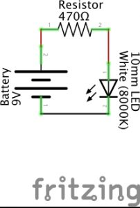
are commonly used to draw out the path used by the electronic components to complete a circuit.
As an example, the Fritzing image above is a schematic with three electronic components:
- a battery
- a resistor
- a
The lines between are not electronic components, but rather are some form of conductive material like a metal wire that is used to carry the current from component to component. In the schematic, a positive current leaves the 9 volt battery and passes through a 560 ohm resistor before connecting to the positive charge of a 10mm white LED. From there, it passes through the negatively charged leg of the LED to the ground connection of the 9 volt battery, completing the circuit. Only when this circuit is fully and properly completed and the battery has sufficient charge to dispatch a current will the LED turn on. (Schematics and diagrams in this book were primarily created using the open source program Fritzing.)[1]
Schematics don’t tell us anything about how the circuit is actually built, and indeed the visuals for the different components needed are confusing artwork until their interpretation is provided. But with a little bit of practice, schematics become a unique conceptual information source. We can use design thinking and rapid prototyping to physically make the circuit using specific parts on hand or acquired to achieve something we value, even if it’s just good enough to help more than bother us.
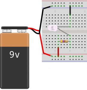
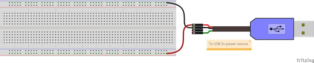
Often times, when you look for a plan or pattern to use electronics to perform a certain task, instead of a schematic, you’ll find a physical diagram of the parts as demonstrated in the Fritzing image shown above. This diagram is based on someone’s layout choices using available components to actually implement the circuit drawn in the Fritzing schematic at the start of this example. In the physical diagram, we see electrical components connected using a solderless , a plastic board with conductive clips under groupings of plastic holes, thereby allowing the passage of current between components.
At the left of this particular diagram, a red wire brings the positive current of the battery to the lower red rail of the breadboard. Another red wire moves it from this rail to row J, column 59. Row H, column 59 then connects the current to one leg of a 470 ohm resistor, which carries that current, now under resistance, to row H, column 55. This brings the current to the positive charge of a 10mm white LED. Row E, column 55 is connected to the negatively charged leg of the LED, which then passes to row A, column 55 where it is connected to a black wire that carries the current to the upper blue rail on the breadboard. A black wire then brings the current to the ground connection of the 9 volt battery, completing the circuit.
As you move forward, you may find yourself exploring and evaluating a variety of online guides, resources, and examples and comparing them to what is shown in the book. (Indeed, take a deep dive through the many examples found at Adafruit Learning System, from which we draw many for this book, for an extraordinarily wide range of electronic systems, along with supporting code.) Sometimes you may find schematics. But more often you’ll find diagrams illustrating how someone or a group have put the circuit into practice. Know that diagrams may be rigid as they tend to focus on a specific task in a specific configuration in a specific environment that suits a specific cohort, community, or culture. Schematics, on the other hand, are found in more professional settings and as such can be applied to a greater range of applications. These schematics, after doing research to define the components illustrated using specific visualizations, will also prove very helpful for problem solving or rapid prototyping for all innovators, regardless of experience.
It may be helpful to think of schematics as standards used for many different applications, projects, and occupations. Schematic drawings are relevant for many users from electrical engineers to K-12 students. For example, circuits and schematics are part of the Next Generation Science Standards (NGSS) Energy Unit for elementary school students in grade 4.[2]
Underneath the Hood of the Breadboard
A solderless breadboard is a plastic board used to create models or prototypes of an electric circuit. They’re solderless because you can easily push wires into the provided holes and later pull them out to move them into new configurations. They come in different shapes and sizes. The most commonly used “full sized” breadboard is 6 1/2″ long and 2 1/8″ wide.
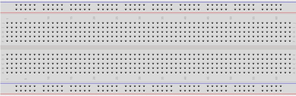
Below, you’ll note several different images of a full sized breadboard. In the first image, you see the typical working view of the breadboard.
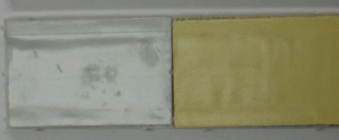
In the next image, we see the bottom side of a breadboard. The left half of the center image has the sticky covering revealed, while the right half has the protective covering installed. If the breadboard is moved around a table or desk, a protective covering remains on the underside of the breadboard (seen in the right half of the center breadboard). You can remove that covering to enable the breadboard to stick to a surface (seen in the left half of the center breadboard).
In the breadboard image below, we see the underside of a breadboard, but this time with the sticky tape fully removed. Breadboards typically come with rails along the edges, with conductive metal clips (two of which are shown at the very bottom of the image) installed so as to carry the flow of current along the extent of each rail.
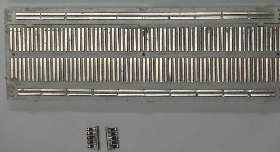
If you compare this image of the breadboard metal clips to the image of the top side of a breadboard, you’ll note there’s a red colored rail and a blue colored rail on the upper part, and another red rail and blue rail on the lower part of the breadboard. The red rail is typically used to carry a positive source to a circuit or series of circuits, while the blue rail is typically used to carry the circuit or series of circuits to ground. The main part of the breadboard connects together groupings of five holes using 126 conductive metal clips.
Thus, column 1, row A is connected to rows B, C, D, and E of column 1 with one metal clip. Column 1, rows F, G, H, I, and J are interconnected with a second metal clip. Column 1, rows A, B, C, D, and E do NOT connect with column 1, rows F, G, H, I, and J by default. They will only interconnect if a wire or electronic component is plugged into one of the left holes of column 1 and also to one of the right holes of column 1, and is set to pass a current from one connection to the other.
Exercise: Building and Testing an Electronics Prototyping Platform
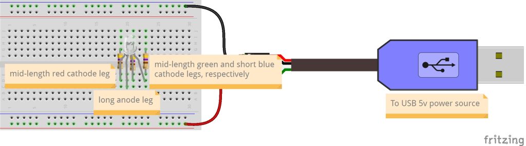
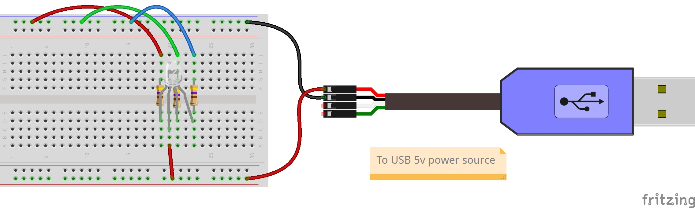
In the previous example, a circuit was created using a 9V battery, as shown in both a schematic and a diagram. Throughout the rest of this book, we will typically not use a battery to power our electronics. We’ll start by using the USB to TTL cable that comes with the toolkit, allowing us to connect the USB side to a 5-volt power source. The 5-volt power source itself is likely connected to either a 120- or 240-volt power alternating current (AC) source, which it inverts to 5-volt direct current (DC) power. The TTL side of the cable will only be used for now to provide power through the red cable and ground through the black cable. Later in the book, we’ll also use the white transmit cable and green receive cable to facilitate data communications between devices.

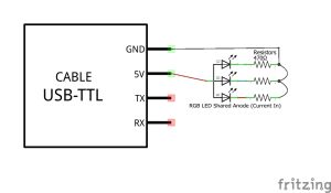
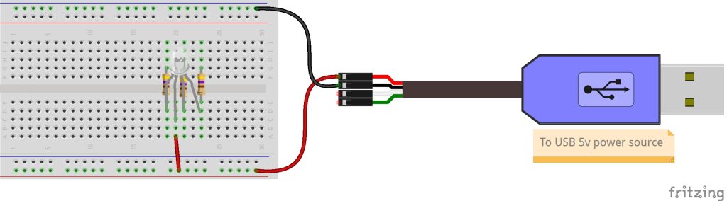
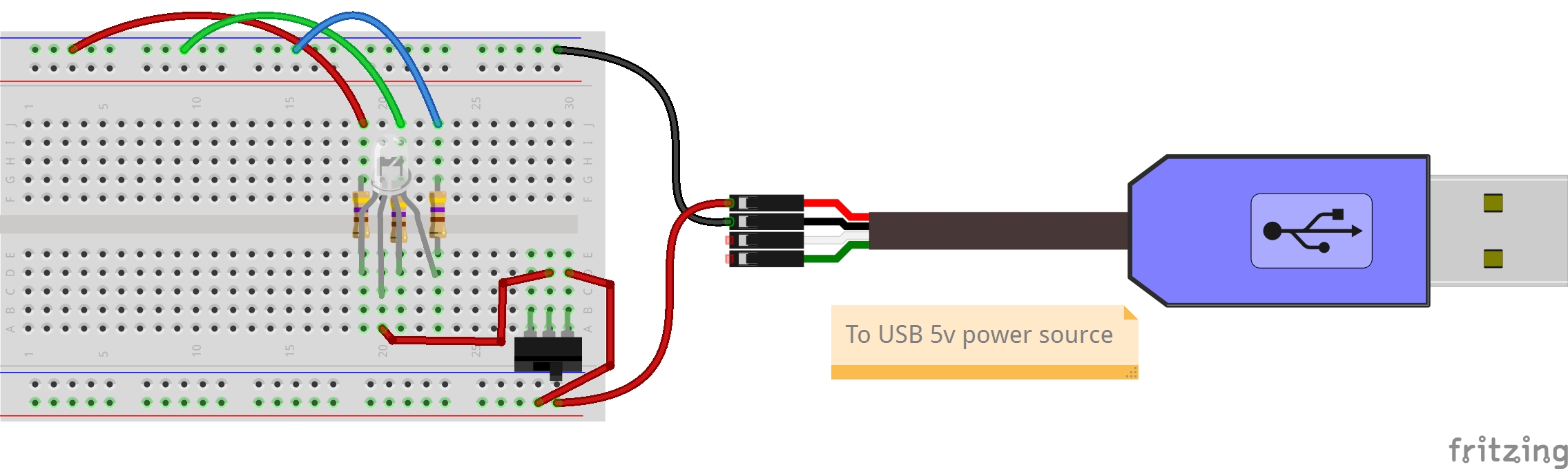
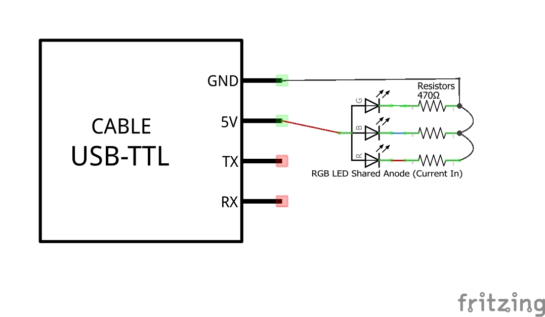
The image above provides a diagram of the basic configuration of our prototyping breadboard, in which power is provided using a USB to TTL cable from the toolkit. The basic circuit located on the breadboard illustrates how 5 volts of current pass through conductive material from the USB to TTL cable, conductive material within the breadboard, and jumper wires to an electronic component called an LED, before returning through additional resistors to ground, thereby completing the circuit.
In the above diagram, it is important to note that the only electronic components are the 470 Ω (ohm) resistors and the Red/Green/Blue (RGB tricolor) LED. The breadboard, jumper wires, and USB to TTL cable are not electronic components, but rather are forms of conductive material used to carry the current from component to component.
Another way to illustrate a circuit is with the schematic below, helping to visualize the single physical LED as three separate functional LED chips incorporated into a single package. Each of the three LED chips are themselves small materials in which a Light Emitting Diode electronic component can be embedded.
In the schematic, there are several standard symbols used:
- The United States standard symbol for a resistor;
- The symbol for a light emitting diode;
- The symbol for a connecting lead;
- The symbol for a junction of conductors; and
- The symbol for an integrated circuit.
For some, such as an (IC) schematic, IC subcategories are further developed for the specific specialty component being used, as is the case for the USB-TTL Cable from Adafruit.com. Inside the blue USB plug case is a USB↔Serial conversion chip that can work with drivers to provide (UART) communications which we’ll start using in this exercise.
Together, these standard symbols are a helpful way to view both diagrams and schematics when starting a new electronics project.
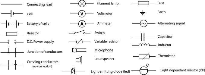
In the above figure, you’ll see a range of symbols commonly found within schematics and diagrams. Note that in this chart, the resistor schematic is a bit different from the one found within the Fritzing schematic for this exercise, as the Lumen Learning modules use the European standard. The Fritzing diagram uses the symbols common within the United States. While most are the same, a few, like resistors, do differ[3].
For the breadboard exercises in the book, we will be using a RGB (red/green/blue) LED. This three-in-one makes use of one leg that can either be the common with a shared power source for the RGB legs, or the common leg with a shared ground source for the three LEDs.
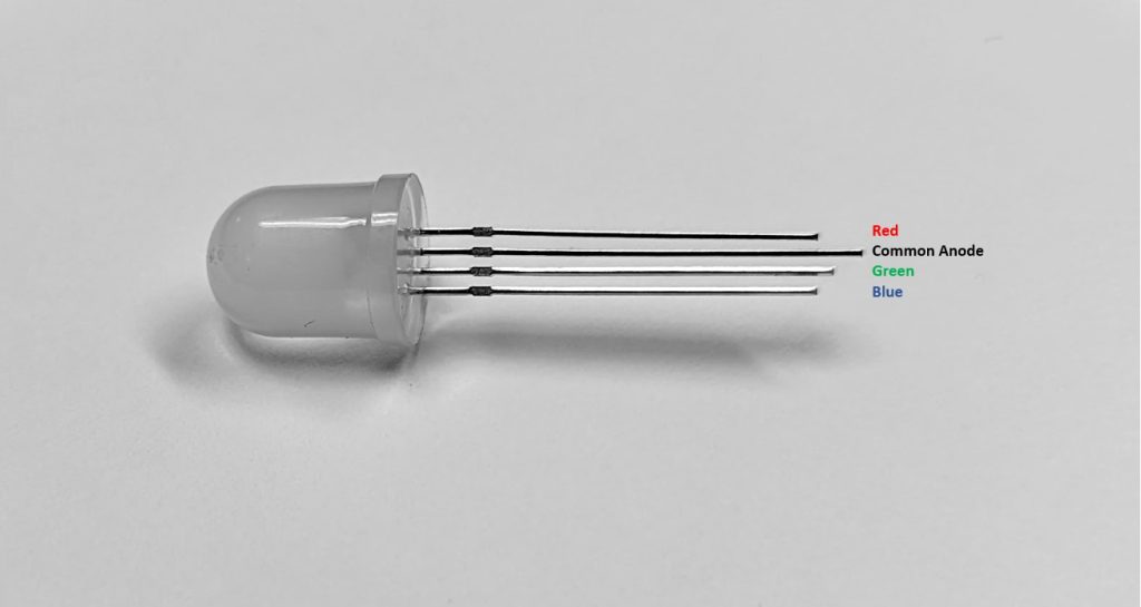
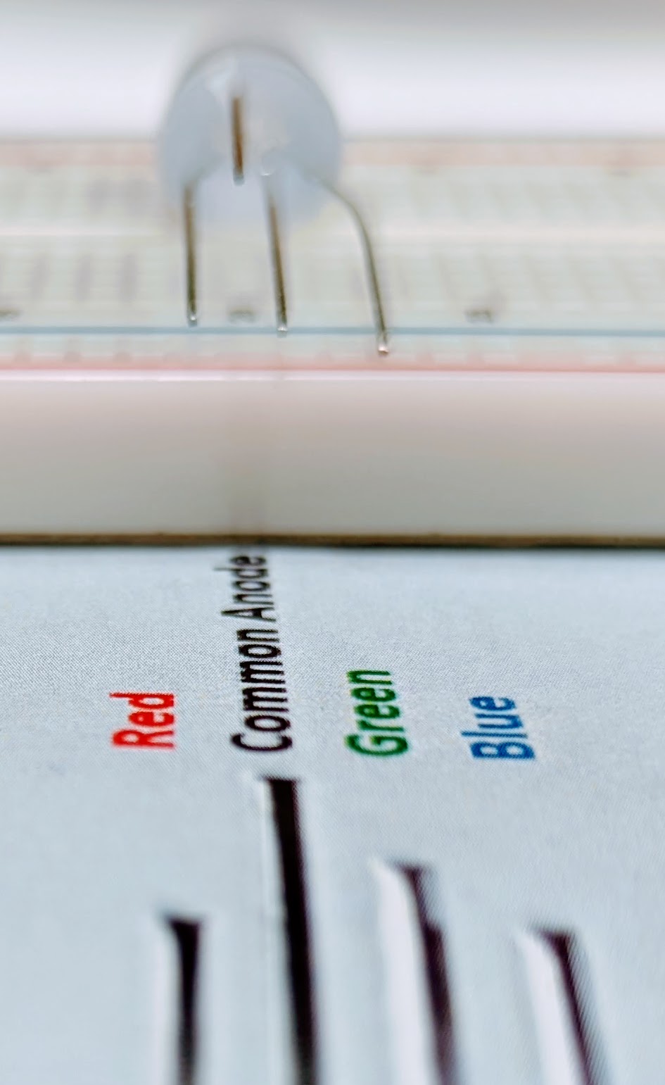
For exercises throughout this book, we are using the diffused RGB (tri-color) 10mm LED with common anode from Adafruit. The anode (longest) leg can accept up to a 5-volt power source. The anode leg then connects to each of the red, green, and blue LED “chips” (“chip” is another term for an ). Each chip connects to its own metal wire, which serves as the cathode leg for that LED. For exercises within this book, we then individually return each chip to ground in parallel through three resistors.

In the image above, you will find the shorter red cathode metal leg at the top, then the long anode metal leg, the middle-length green cathode metal leg, and finally the short blue cathode metal leg at the bottom of the image.
Steps
- Take the needed parts out of the toolkit:
- Full-size breadboard (illustrations will use either a half- or a full-size breadboard for better visualization of a given step)
- USB to TTL cable
- RGB LED
- Three 470 Ω or 560 Ω resistors
- Six male/male jumper cables. Cables, breadboards, and other conductive materials have one of two different end connector types:
- Male-type ends have an exposed conductive metal extending beyond the protective case.
- Female-type ends have a conductive metal hole within a plastic or other non-conductive case into which a male end is inserted.
- Connect the TTL to USB cable on the far right of the breadboard to provide 5-volt (5v) and ground (GND) sources to the board. In the illustration below, you’ll notice the Fritzing software tool used throughout this book for electronics design projects provides a green highlighting of all female holes, which are also now accessible to the male end which was inserted into one of the holes in the conductive series.
- Position the breadboard with column 1 towards your left.
- Use a male/male jumper cable to connect the female 5-volt (red) TTL connector of the USB to TTL cable to the lower red rail of the breadboard. The above illustration highlights that all holes along this red rail can now be used to connect to this 5-volt power source.
- Use a male/male jumper cable to connect the female ground (black) TTL connector of the USB to TTL cable to the upper blue rail of the breadboard. The above illustration highlights that all holes along this blue rail can now be used to connect to this ground source.
- NOTE: The color-coding of jumper wire insulation does not impact the conductive capability of the copper wire within the insulation. However, it is often used strategically and sometimes through coding standards to indicate a purpose.
- In the context of the breadboard and USB to TTL cable, red is commonly used to indicate a power source within a direct current (DC) circuit, while black or blue are used to indicate ground.
- In the context of the book, it is also used to indicate the red, green, and blue legs of the RGB LED.
- In practice, packages of jumper wires may be all of the same color or only a few different colors, and can be used as availability dictates.
- Depending on the type and level of color blindness, some individuals may need a mix of diverse individual and collaborative approaches to fail forward. This may include strategic color-coding selection, process of elimination, and labeling.
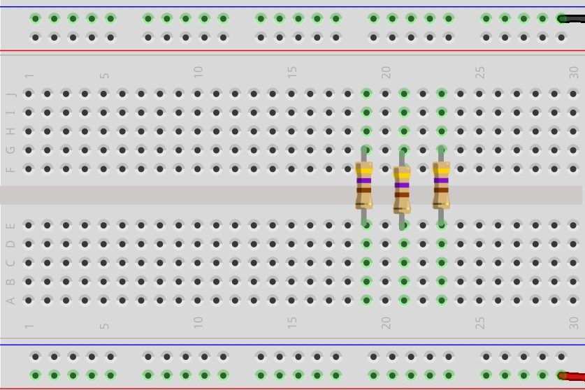
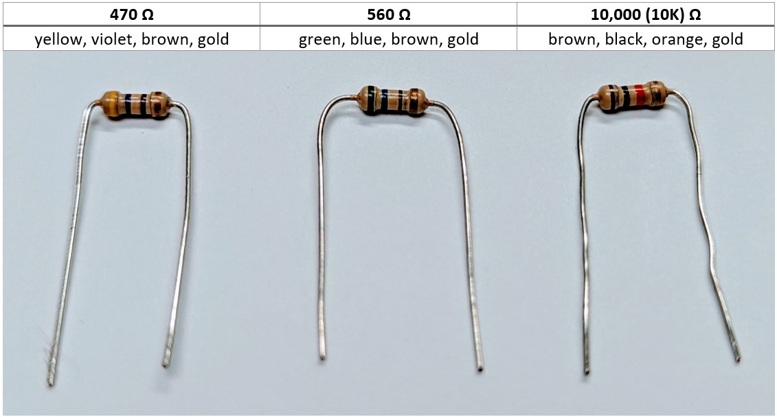
- Install three 470 Ω resistors on the breadboard.
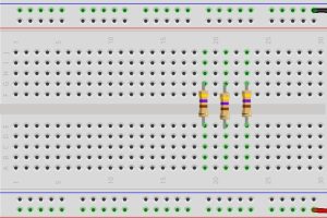
- Tightly bend down 90 degrees the two legs of each 470 Ω resistor.
-
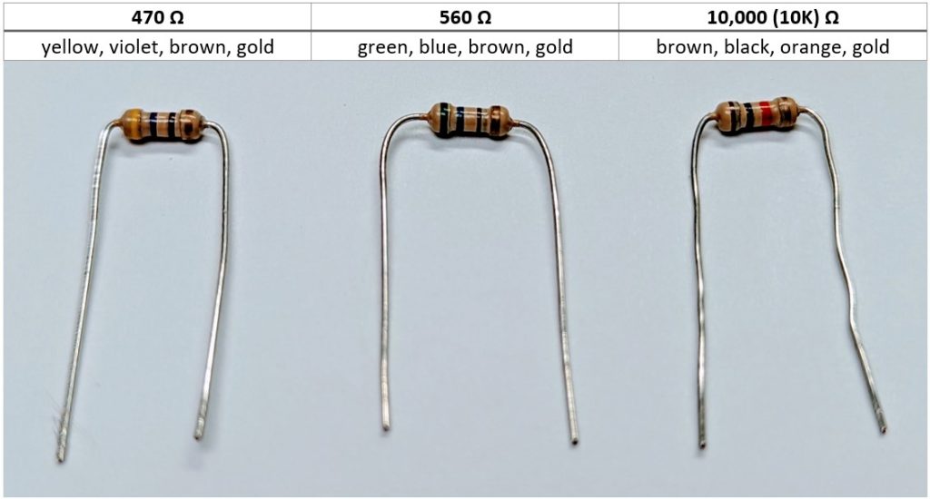
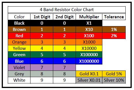
- These are resistors with yellow (associated with the number 4 in the 10s column), then violet (associated with the number 7 in the 1s column), then brown (associated with times-10 multiply column) bands and are followed by a gold tolerance band.
- You can also use 560 Ω resistors with green (number 5 in the 10s column), then blue (number 6 in the 1s column), then brown bands. The 560 Ω resistors come with some Raspberry Pi Starter Packs and are very similar in resistance capacity to the 470 Ω resistor used in this book.
Resistors come with standard 4- or 5-band color coding. This may prove a challenge for those with a color vision impairment.
-
- Attach one leg of the resistor to row E, and the other to row G or thereabouts. One resistor will be in column 19, one in column 21, one in column 23.
-
- Each resistor will provide a small amount of resistance to the current, leaving the red, green, or blue legs of the RGB LED on its way to ground and completion of the circuit.
- As a reminder, rows A, B, C, D, and E have a metal conductor connecting each together within a given column. Likewise, F, G, H, I, and J have a separate metal conductor connecting each together within a given column. A-E is NOT connected to F-J within a given column by default.
- We will use three 470 or 560 Ω resistors to connect the lower A-E part of the column, to which an anode leg of the RGB LED is connected, to the upper F-J part of the same column. Fritzing highlights such connections in green within their illustrations, although in practice, unused holes remain the same dark color whether or not other associated holes on a conductor now have a conductive wire or electronic component attached.
-
- Tightly bend down 90 degrees the two legs of each 470 Ω resistor.
- Install the RGB LED on the breadboard
- Pick up the RGB LED and hold it in your hand matching the order seen in the image below, such that the short red cathode leg is at the top, the long anode leg next, followed by the mid-length green cathode leg, and finally the blue cathode leg at the bottom.
- Bend the mid-length red cathode leg up slightly, and then return it to the right.

- Bend the long anode leg away and then return it to the right.
- Keep the mid-length green cathode leg as is, facing straight to the right.
- Bend the short blue cathode leg down and then return it to the right.
- Turn the RGB LED so that the red cathode leg faces left and the common anode leg faces up from the breadboard. Insert the four legs of the RGB LED into the breadboard such that the red cathode leg is in column 19, row D, the anode leg is in column 20, row C, the green cathode leg is in column 21, row D, and the blue anode leg is in column 23, row D.
- Pick up the RGB LED and hold it in your hand matching the order seen in the image below, such that the short red cathode leg is at the top, the long anode leg next, followed by the mid-length green cathode leg, and finally the blue cathode leg at the bottom.
- Connect the USB side of the USB to TTL cable to a 5-volt USB power source, such as your laptop, or a 120/240-volt power source with power adaptor for a USB connector.
- Provide 5-volt current to the shared anode leg of the RGB LED.
- Connect one leg of a male/male jumper wire to the bottom red rail, and the other leg of the jumper wire to column 20 (the same column as the anode leg), row A.
- NOTE: The circuit is not yet complete, as the 5-volt power now flowing from the USB to TTL into the red rail of the breadboard and then to the anode leg of the RGB and out through the cathode legs and through the three resistors does NOT reach the blue ground rail of the breadboard, and thereby does not return back to a ground source.
- Connect one leg of a male/male jumper wire to the bottom red rail, and the other leg of the jumper wire to column 20 (the same column as the anode leg), row A.
- Complete the circuit by returning current from each cathode leg of the RGB LED to ground.
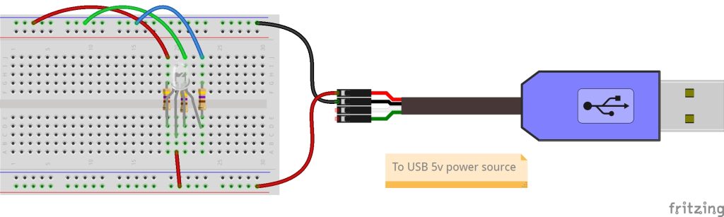
- Connect three male/male jumper wires from the blue ground rail at the top to row J of columns 19 (red cathode leg), 21 (green cathode leg), and 23 (blue cathode leg).
- What happens when only one jumper wire is connected between the resistor and ground at a time?
- What happens when two jumper wires are connected at a time? All three?
- How many different LED colors can be achieved with these three base LED colors?
- Does the brightness of the LED change depending on how many circuits are plugged into a USB hub? Into a USB 1, USB 2, or a USB 3 port on a laptop? Into another USB 5-volt power source?
- Connect three male/male jumper wires from the blue ground rail at the top to row J of columns 19 (red cathode leg), 21 (green cathode leg), and 23 (blue cathode leg).


Key Takeaways
In this exercise, we’ve entered into a first apprenticeship crafting a , using a USB to TTL cable as a source for power and ground, and using a breadboard as the physical prototyping base tool. To do this, we brought together several wires, like the male-to-male made of individual wires. To test this platform, we brought together two electronic components, a and a RGB , to provide some literal light on the platform.
In addition to these technical skills, we sought to bring in the development of several socio-emotional skills, including the ability to communicate and collaborate with others using a “see once, do once, teach once” strategy using pair/triplet programming, and potentially began exploring how failure serves as an essential step in project development—that is, a fail-forward mindset.
It’s also helpful to think about our daily use technologies as devices that use a specific form of thinking called deductive reasoning. The bigger picture is broken down into the smallest possible parts needed to best succeed with the least amount of work. At the initial design phase, the questions focus on doing the most with the least number of components. On the other side of the coin, the instructions for others to carry out their own building of the electronic device need to also be written using deductive reasoning. Personally, I’ve often found I don’t read the instructions if I can just look at some pictures or watch a video and then work through things myself. But in the electronics realm, this can bring us to “catastrophic” failures in which the components are no longer usable and new ones need to be purchased. Sometimes packages include extra parts in expectation of this happening. But other times, such failure can have unacceptable threats. Consider pilots who have flown thousands of flights, but still go through the reading of a checklist from beginning to end.
While failure is common and serves as an essential step in project development, when might it be helpful to add “read once” as a precursor to “see once, do once, teach once”?
There are many ways to design and build electronic artifacts. This can be done as individuals working to serve personal interests. This can be done as individuals working as experts to serve others broadly considered. This can be done as individuals working as experts to serve others more strategically. It can be done in groups randomly or strategically partnered to serve inwards or to serve outwards. It can be done as a community of practice in ways that include the contributions of a range of stakeholders. And it can be done in so many other ways as well.
- How did you work to do this first hands-on exercise of the book with electronics?
- How did I and others work to develop this exercise? How did it influence your work with electronics? Who else influenced your work?
- What makes an LED and a resistor electronic components? What makes wires, the Cobbler, and the breadboard conductors parts which support electronic components?
Troubleshooting Essentials
Collective leadership and community inquiry using groups of two or three people to collaboratively test out hands-on work brings together the expertise of multiple individuals.. Failure is common, and generally remains the norm, from iteration to iteration for an extended period.
To positively fail forward, our iterations are an opportunity for us to discover how our inspirations and ideations aren’t aligning with our past and current iteration prototype. Reflecting on our actions individually and as part of community inquiry is central to that work of discovery. Said another way, iterations help us see how one part, much, or all of our working idea is falling short of good enough. This helps inspire better ideations and sometimes even new inspirations, ultimately leading to better iterations — at least for us within the given testing context.
Let me say this again: Trying and failing is not optional. It is the norm. The general alternative to failing forward is failing to improve.
Accepting failure as a normal, active, ongoing part of what we do leads us to failing forward in ways that facilitate growth and betterment of ourselves, and when done across functional diversities and community cultural wealth, the betterment of others as well. In so doing, we foster a high performing community of practice.
So let’s assume the LED did not light up in the last exercise, or that it burned up in the last exercise, or that it won’t light up in the next exercise. Why not? What happened?
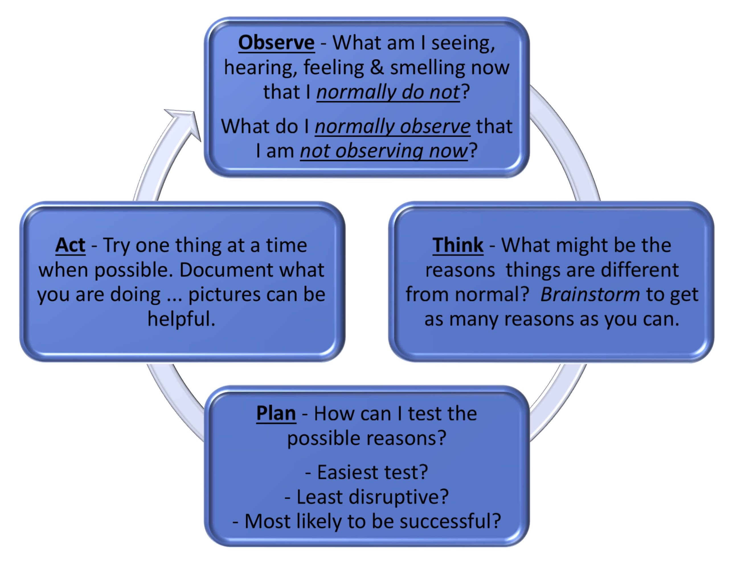
Humans and other more-than-human persons around us have a rich range of analog senses, such as sight, hearing, feeling, and smelling. These are a wonderful resource in the troubleshooting process. These analog senses provide a continuously variable physical quantity, such as the visible wavelengths of light. This stands in contrast to the digits 0 and 1 that typically represent the values of a physical quality provided by digital measurements.
Bringing our observations through those analog, continuously variable, senses into a process of critical thinking helps us create a plan for testing out a range of possibilities. Enacting that plan one step at a time helps us to continue the cycle of observation, thinking, planning, and acting. This is the heart and soul of inquiry-based learning as we collaborate in pairs and small groups through dialogue.
Throughout the remainder of the exercises in this book, and as you work through your own design activities putting your learning into practice, be sure to make extensive, preferably documented, use of these troubleshooting basics. It’s tempting to try it a few times and move on because troubleshooting the current exercises begins to become second nature. These experiences serve as a learning opportunity, but at the risk of having the learning become hidden knowledge that fails to fully help you as you encounter future problems.
Indeed, this is a reason why this book has been written using the Creative Commons Attribution-ShareAlike license. We hope you will add in annotations, page notes, and remixes for yourself and others to use as sources for their own design thinking projects. We hope the resulting inspirations, ideations, iterations, and failures support an advancing betterment of ourselves, those in our community of practice, and those we are serving through our creative works.
Exercise: Adding a Two-position Switch to Our Circuit
In this activity, we will add a slide switch into our circuit. It is called a “switch” because it changes the flow of current depending on the state of the switch. This switch creates a change in state when a physical action happens—in this case, when a slider is moved to the left or to the right. This type of single pole, double throw (SPDT) switch is a great electronic component to turn something on and off, or to select between this or that. The center pin provides the rest of the circuit with the results of the user’s choice. The left and right throw pins provide the user with one of two options. We’ll be using this switch in a variety of ways moving forward. For now, we’ll connect the single center pole to the RGB LED, and the right pole to the lower red rail providing a 5-volt power source. The left pole will be left open. The user then chooses between providing the RGB LED with 5 volts of power (on state) or no power (off state). When the slide is to the left, we have a because the switch creates a state in which power completes circle over to ground is complete. When the slide is to the right, we have an open circuit because there is no starting power needed to begin the flow of current required for a completed circuit.
Steps
- Attach a slide switch to columns 28, 29, and 30 of row B.
- Connect one end of a male/male jumper wire to column 20, row A, and the other end to column 29, row D. This is the common leg of the slide switch.
- Connect a second male/male jumper wire to the lower red rail. The other end of this jumper wire gets connected to column 30, row D. This is the right selection leg of the slide switch.
- Finally, make sure the TTL to USB is plugged into a power source, and then slide the switch left and right to turn the RGB LEDs on and off.

Key Takeaways
Designing and building electronic devices needs to include consideration of the mundane—for instance, turning something on or off. In this second exercise, we’ve further explored how conductive materials like a breadboard and jumper wires can be combined with electronic components like a slide switch to provide the users of an electronic device with such on/off choice. But while mundane, there are still key aspects shaping the layout.
- Why might it be that I put the switch where I did?
- Does the placement work well for you when you work to move the slide left or right?
- Is there someplace else on the breadboard where you might have placed the slide switch?
If possible, jot down your answers to these reflective question prompts so that you can revisit the questions and your answers later. Doing so is an essential part of action-reflection cycles that help bring a new lens of understanding on sociotechnical artifacts such as the electronic circuits we’ll be building throughout the book.
In writing the exercises of this book, I shaped the design of the device for a range of functional, socio-emotional, and cognitive reasons. As you build it, you have the agency to further shape the design as you read through and implement the steps of the current activity. Taking time to reflect on actions and to make a recording of those reflections helps to keep an ongoing account of your socio-technical praxis as you exercise that agency to innovate-in-use, or stick with the instructions as written, or discover a mistake in the instructions, or make a mistake following those instructions. Reflections like this go on to provide opportunities not only for you, but for others in a community of inquiry to go beyond finding and using information. It is in action-reflection that we move collectively from holding information to advancing a better understanding of the information and of the people and contexts shaping that information.
Voltage, Resistance, and LED Brightness
Earlier in this chapter, we covered a bit on , which provides a basic equation I=V/R stating that (I) is equal to (V) divided by (R). Voltage is like the pressure of water in a hose. Current, measured in amperage, or amps for short, is like the flow of water through a hose. The thickness of the hose impacts the resistance of the flow of water through it, which is like the ohms of resistance in a circuit.
Let’s take the water analogy one step further. Imagine the water is now used to turn a wheel, which is used to power a small mill making gristmill, which is used to turn cereal grain into flour. You can increase the power generated by the water wheel by either increasing the pressure (voltage) of the water or increasing the flow (amps) of the water. In electrical terms, this power (P) is called wattage, or .
The formula for this is Volts x Amps = Watts.
Some may be familiar with, and perhaps make regular use of, lighting in which you can control the brightness of the light. Perhaps you have a lamp with a three-way light bulb providing three different watts of power, depending on the position of a rotary switch. Each turn of the light switch steps you up to the next wattage before returning to off. The lightbulb may state that it is a 60/120/180-watt bulb. If you are in the United States, you likely plug this lamp into a 120-volt outlet. We now are using one of three amps of current
- 60 watts / 120 volts = 0.5 amps
- 120 watts / 120 volts = 1.0 amps
- 180 watts / 120 volts = 1.5 amps
If our 120-volt outlet is listed as being a 15-amp circuit, we should keep in mind that if all these lamps were running at full wattage, we should have a maximum of 15 amps / 1.5 amps = 10 lights at 180 watts.
Let’s look back at our RGB LED. It is rated for a maximum of 5 volts. Adafruit has a USB 2.0 Powered Hub with 7 ports, each with 5 volts at 2 amps. If we were using this for our RGB LED, the common anode would be receiving
5 volts x 2 amps = 10 watts of power
But given we have a 470 Ω resistor wired to each cathode leg to assure it doesn’t get so much current that it burns out, each of the parallel circuits is reduced a bit, as we see in Ohm’s law (I=V/R):
5 volts / 470 ohms = .01 amps
5 volts x .01 amps = .05 watts
To demonstrate, four parallel LED circuits have been created, each receiving different amps of power, thereby providing different watts of light. The breadboard circuits use the following components:
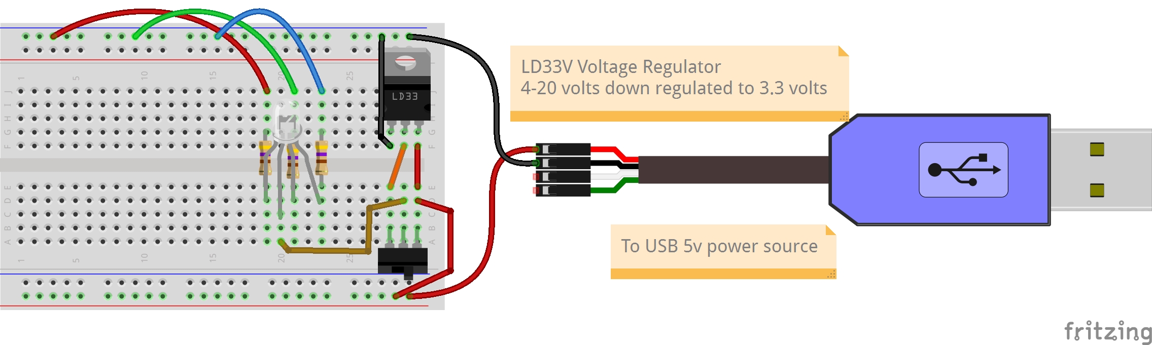
- A USB to TTL connected to a USB 2 powered hub providing 5 volts at 2 amps. This is attached to a full-sized breadboard as before.
- A voltage regulator, an electronic component that brings the voltage of a power supply down to a level compatible with the other electronic components. Here a voltage regulator is being used that can work with 4-20 volts of DC power as the source (in our case, 5 volts at 2 amps), which it then regulates down to a stable 3.3 volts DC power.
- Two 470 Ω and two 10,000 Ω resistors
- Four 10mm bright white LEDs
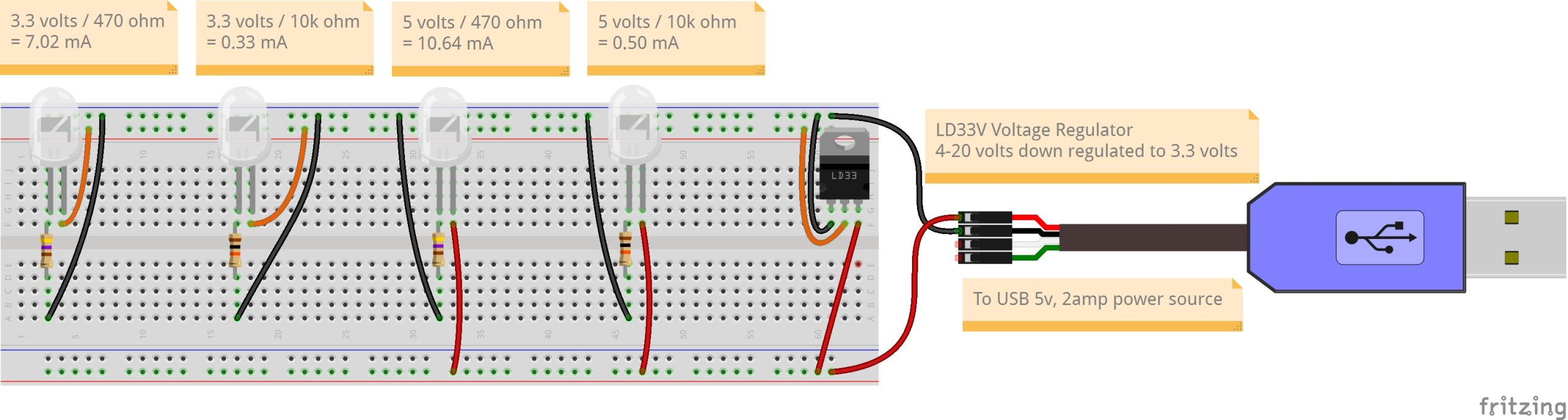
From left to right, the watts of power of each LED in the image above are as follows:
| 3.3 volts / 470 ohms = 0.0070 amps = 7.0 mA | 3.3 volts x 0.0070 amps = 0.0231 watts = 23.1 mW |
| 3.3 volts / 10,000 ohms = 0.0003 amps = 0.3 mA | 3.3 volts x 0.0003 amps = 0.0011 watts = 1.1 mW |
| 5 volts / 470 ohms = 0.0106 amps = 10.6 mA | 5 volts x 0.0106 amps = 0.0532 watts = 53.2 mW |
| 5 volts / 10,000 ohms = 0.0005 amps = 0.5 mA | 5 volts x 0.0005 amps = 0.0025 watts = 2.5 mW |
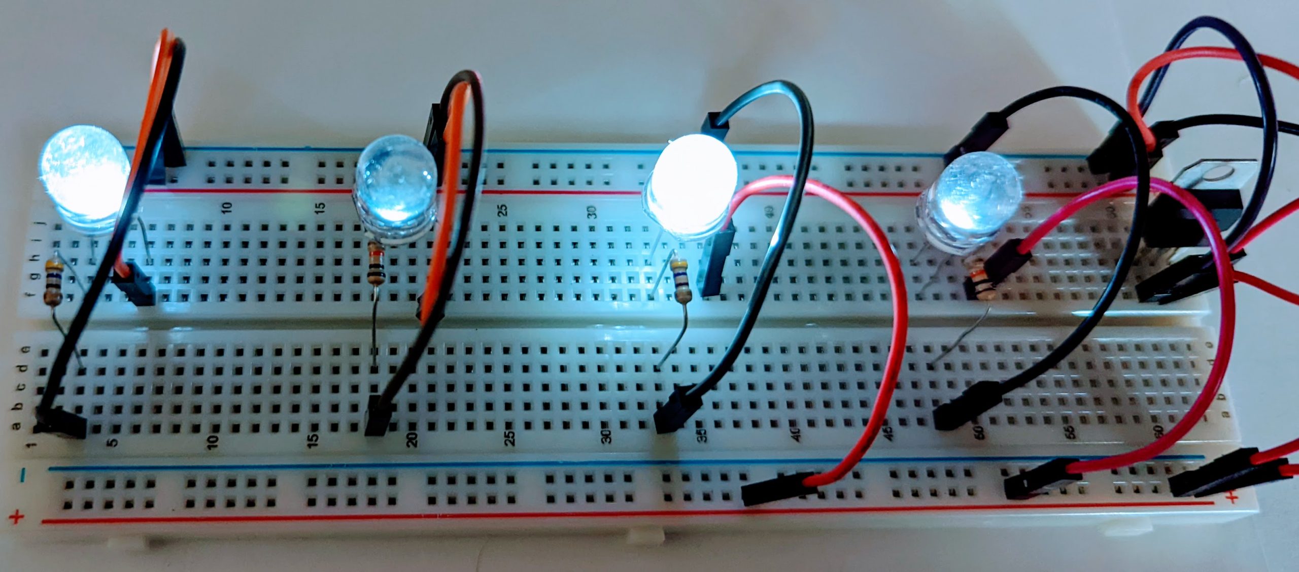
These are clearly not nearly as bright as a 60-watt light bulb in a house! But as the plastic cases of each of these bright white LEDs are not diffused like the diffused RGB LEDs we’ve been using, we can see how much more they brighten the view of the breadboard, especially the 1/20th of a watt from the 5V + 470 Ω LED circuit.
Do Something New!
For some, this is your first journey into electronic circuits. You’re Doing Something New through troubleshooting electronic circuits and failing forward! You are at a “yet-enough” point to head on down to the Wrap Up and Comprehension Check at the bottom of this chapter.
For others, you may already have a lived experience with electronic circuits. This is not something new to you. But if you’re at all like me, some of this work has become rote, and the underlying terms, concepts, and principles hidden knowledge. For you, Doing Something New may be a work of re-remembering the codes to the electronic wheelhouse. And moving beyond, maybe it’s discovering some of the social influences that have shaped the non-neutral aspects of the otherwise strict laws of physics within.
For all, it’s likely that at least some aspects of Collective Leadership, Community Inquiry, Action-Reflection, the Information Search Process, and Pair/Triplet Programming are new to you. Do Something New! by incorporating one or two of these into your work, this and every session, individually and as part of your Community of Practice work.
Below are two Do Something New! exercises putting the above brightness display into practice using your own starting breadboard circuit prototype, this time using the RGB LED. How much do they change the brightness of red, green, and blue diffused LEDs? For those not yet ready to take on the exercises but still wanting to dig a bit more into what’s behind the hood, you can also skim one or both activities themselves and then delve more into the Key Takeaways of each to advance from understanding less to understanding more.
Exercise: Using a Switch to Compare Differences in Resistance of Current Flow
In setting up our parallel red, green, and blue RGB LED circuits, each cathode leg is passed through a 470-ohm resistor on the way to ground. The change in amps remains the same whether the resistor is placed before or after LED within a circuit, in this case 5V/470 Ω = 0.01064 amps (10.64 milliAmps or mA). The switch is currently used to select between “on,” in which case 10.64 mA sent to the common anode leg of the RGB LED, or “off,” in which case no current is sent to the RGB LED.
In this Do Something New! activity, we’ll add a new 470 Ω resistor to the left throw pin of the slide switch. This resistance will be added to each of the three cathode legs so that all three LEDs now pass through 940 ohms of resistance. Using Ohm’s law, 5V/940 Ω = 5.32 mA, or half the 10.64 mA sent to the common anode leg when the slide switch is to the right.
Steps
- Tightly bend down 90 degrees the two legs of a fourth 470 Ω resistor.
- Insert one leg of the resistor in column 30, row H, and the other in column 26, row H.
- Connect one end of a male/male jumper wire to column 30, row E, and the other end to column 30, row F. Now current from the red power rail is passed to rows A-E of column 30, the jumper wire attached in step 1, and to rows F-J using a second jumper wire we just installed as part of step 2.
- Connect one end of another male/male jumper wire to column 26, row F, and the other end to column 28, row E. This is the left selection leg of the slide switch.
- Finally, make sure the TTL to USB is plugged into a power source. Then slide the switch left to examine the brightness of the RGB LEDs when the current passes through an additional 470 ohms of resistance before entering the shared anode leg of the RGB LED. Compare this to the brightness of the RGB LEDs when current enters directly to the shared anode leg of the RGB LED.
- This change will impact the red, green, and blue LEDs differently, as each of these light-emitting diodes work within different ranges. Plus, red alone is different than red plus green, which is different from red plus green plus blue. Try different combinations of red, green, and blue circuits connected to ground to fully test the differences.
- If you can, take pictures of the RGB LED circuit with the switch to the left and to the right so that you can more readily compare the differences between them.
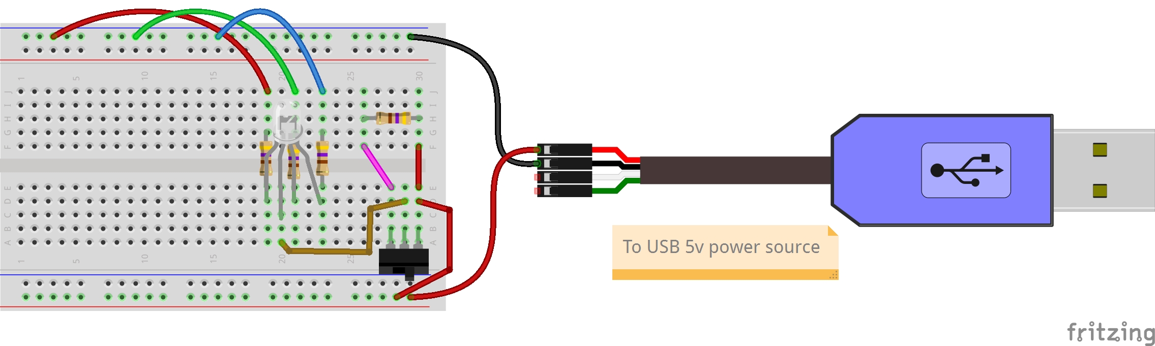
Below, you can see the schematic of our new circuit, which you can compare to the Fritzing diagram above. Looking at the standard switch symbol used in the schematic drawing, we see that what passes from leg 2 over to the common anode leg of the RGB LED is determined by the line that rocks between legs 1 and 3 of the switch. In designing this circuit, I chose to connect the 5-volt current directly to leg 1, and to run the 5-volt current through a 470 Ω resistor before connecting to leg 3.

Let’s further compare our switched resistance schematic above with the schematic from the first exercise, in which the 5-volt current was connected directly to the common anode leg of the RGB LED. Note that while initially 5 volts flowed directly from the USB to TTL cable to the common anode leg of the RGB LED, it now first flows through a slide switch, in which it either passes directly to the common anode leg or passes first through an additional 470 Ω resistor before reaching the common anode leg.
Key Takeaways
Resistance is a common way to control the brightness of lights. In our breadboard prototype, resistance changes the flow of current from source into the common anode leg of the RGB LED, and out to ground by way of the red, green, and blue cathode legs. We have already included 470-ohm resistors in our red, green, and blue circuits, to assure that the flow of current when connected to a 9-volt battery does not exceed the amount of current listed within the current rating of the RGB LED we’re using. (This is a general introduction—for more on current ratings of LEDs and how to use this to select power sources and a resistor for a circuit, I highly recommend “All About LEDs” by Tyler Cooper.) While it is essential that you include at least the minimum required resistors within your circuit, resistors are often used to intentionally restrict the flow of current further than required, as a way to control the brightness of light provided.
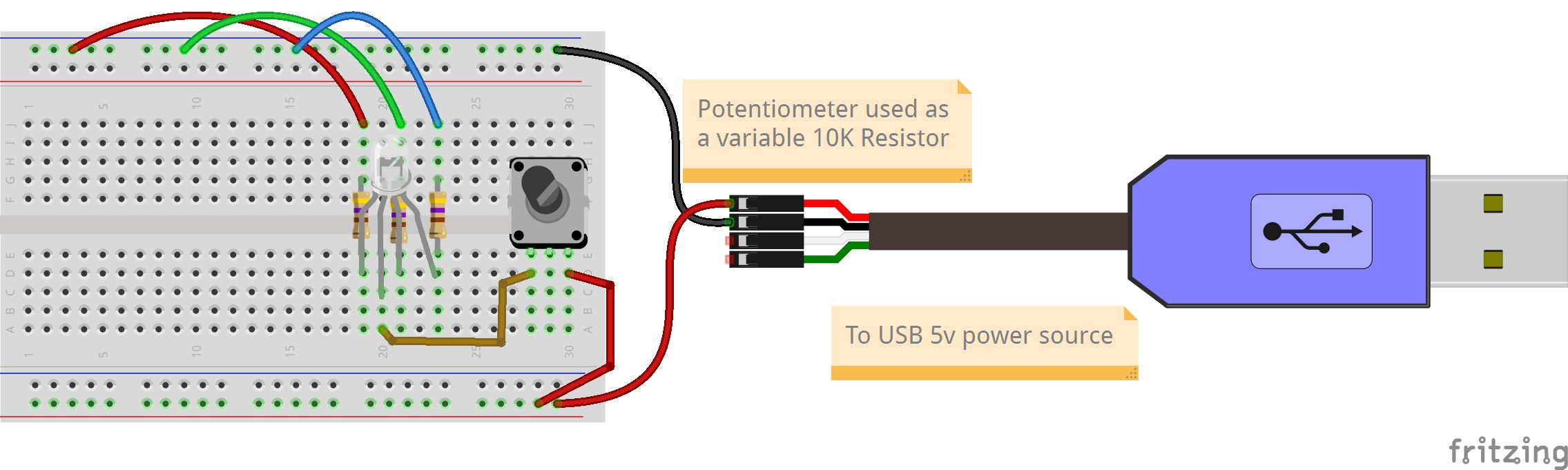
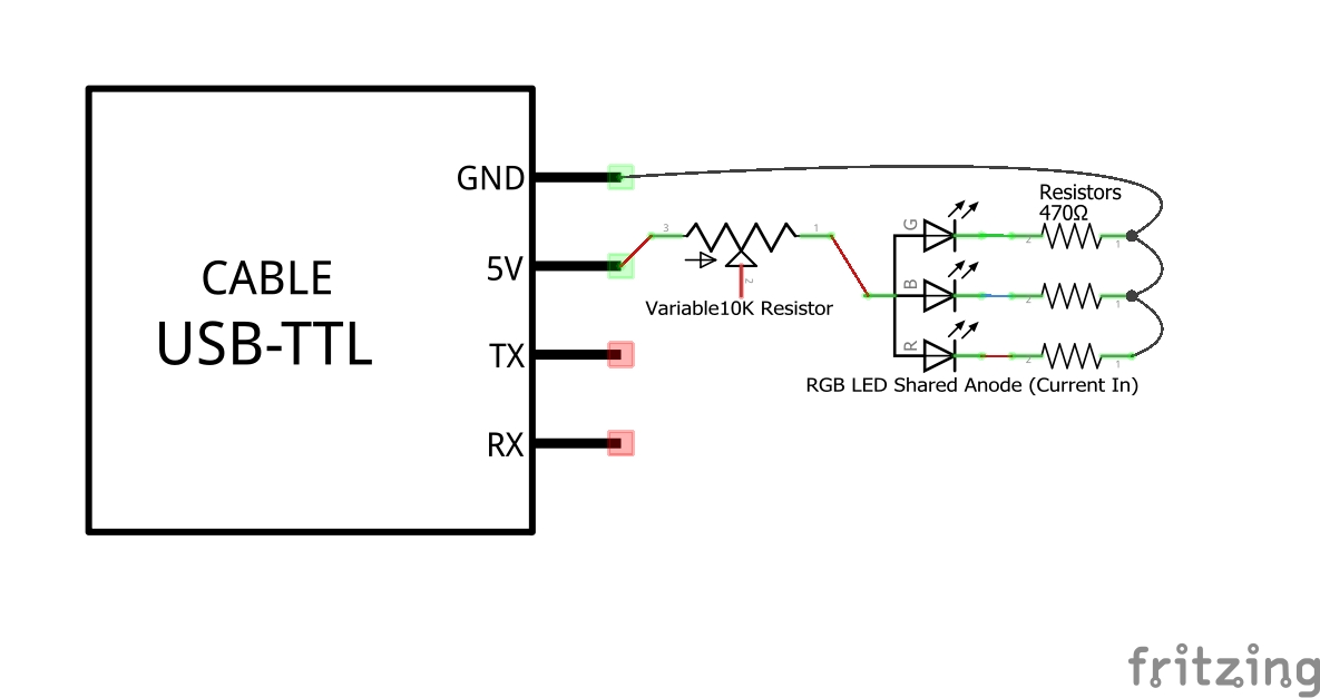
The flow of current can be controlled using many different types of switches. You might have lights at home that can be dimmed. Your mobile phone might let you use a slide to control its brightness. Or you might be able to enable or disable “nighttime mode” for your clock. When a circuit is designed to provide a steady gradation in resistance, the type of electronic switch commonly used is called a variable resistance potentiometer. Potentiometers slowly change the level of resistance provided from a defined minimum (e.g., 470 ohm) to a defined maximum (e.g., 10K ohm). Below are Fritzing images of a 10K potentiometer that could be used for our testing.
For this exercise, we used an electronic single pole double throw (SPDT) slide switch. The single common pole in our exercise is used to connect to the common anode leg of the RGB LED. The two throw legs are then connected directly to a 5-volt power source and to a 5-volt current that is first passed through a 470-ohm resistor. Selecting one of the two throw legs of the switch chooses whether to provide current directly from the rail or via a resistor. The slide switch was selected as a simple means for comparing two different conditions—this one or that one. In the above, we used it first to choose between off and on. Then we chose between a direct 5-volt connection and a 5-volt connection with 470-ohm resistance. And next we’ll use it to choose between different voltages.
- How does the brightness of the light from the RGB LED—either together or in different combinations or red, green, and blue—change when the slide switch is moved left or right? Why, and how much?
- What are some reasons you can think of that I decided to design the selection and use of the LEDs, resistors, switches, and wires in the way that I did to set up your execution of this activity?
- What are some ways we might have done it differently, and in so doing may have created a better way for you to complete this activity?
Exercise: Using a Switch to Compare Differences in Voltage
For this second Do Something New! activity, let’s use the two-way switch to select between a 5-volt and a 3.3-volt current, to consider how a difference in the voltage of current compares to a difference in the resistance—that is, the flow of current. Today’s USB standard works with 5-volt direct current (DC). Most homes and offices have wall outlets that use 120V or 240V alternating current (AC). A power converter is used to switch from alternating to direct current. 5-volt DC has proved a solid choice for many electronic circuits, but others, like fans and motors, often make use of the widely used 12-volt direct current. And some electronics have worked to reduce power usage by going the other direction, decreasing current to 3.3 volts. Unlike the AC voltage standards used within different countries, the 3.3V, 5V, and 12V DC are not standards, just widely used voltages. When selecting electronic components, it’s important to identify the range of voltages which can be used for that component and to plan accordingly.
The RGB LED we’re using has a maximum forward current rating of 20 milliamps (mA). Looking back at the start of this chapter, we saw a demonstration of a circuit built using a 9-volt battery and a 470 ohm resistor. Together, 9 volts at 470 ohm is 19 mA, just under the 20-mA maximum current rating of many of the LEDs we use today. Using a 5-volt power source, we could have safely gone down to a 100 ohm resistor, but stayed with the 470 ohm resistor in case a 9-volt battery was used instead of a 5-volt USB power source. Together, 5 volts at 470 ohm is 10.6 mA. If we go the other direction, down to 3.3 volts at 470 ohm, we are now at 7 mA, or 1/3rd of the amperage used with 9-volt power and 2/3rd the amperage used with the 5-volt power.
Keeping resistance constant, how does decreasing current usage by decreasing power impact the brightness of an LED? Let’s find out by using a voltage regulator. A voltage regulator is useful when you have a possible range of voltages for a power source, but are needing a stable voltage for your electronics. Look at your laptop power adaptor, and it will likely say it can work within the range of 110V to 240V AC input. It will also list a stable DC output voltage or voltages to be provided regardless of the input voltage.
In our case, we’ll use a voltage regulator that can work with 4-20 volts of DC power as the source, which it then regulates down to a stable 3.3 volts of DC power. To keep this simple, we’ll replace the 10k ohm resistor with the voltage regulator. But this could be connected to its own switch that then feeds into the slide switch used for the resistor to do a 2×2 comparison of resistance and voltage on LED brightness. And as an important side note, the GPIO pins of a Raspberry Pi we’ll be using in session four of the Orange Unit provide both pins with 5-volt power, which they receive from the micro-USB or USB-C plugin and pins with voltage regulated 3.3-volt power, allowing us to bring both to the breadboard for ongoing use. This Do Something New! provides a first glimpse at some possibilities for if we were connected to the Raspberry Pi GPIO instead of the USB to TTL cable for breadboard power and ground.
Steps
- Return to the on/off switch circuit for the RGB LED
- Remove the 470 Ω resistor and associated jumper wires.
- Connect an LD33V voltage regulator such that the LD33V label is facing the switch.
- Use jumper wires to provide the ground and 5V power sources to the regulator, and connect the regulator output to the left throw leg of the switch.
- Finally, make sure the TTL to USB is plugged into a power source. Then slide the switch left to examine the brightness of the RGB LEDs when 3.3 volts of power are provided, compared to when the switch is to the right and 5 volts of power are provided.
- If you can, take pictures of the RGB LED circuit with the switch to the left and to the right so that you can more readily compare the differences between these.
Key Takeaways
This layout of the breadboard now provides an opportunity to compare brightness depending on voltage. For this exercise, we incorporated another commonly used electronic component, known as a voltage regulator, to take the 5 volts of power provided through the USB to TTL cable and regulate it down to a stable 3.3 volts of DC power. As we’ve now seen in these two Do Something New! activities, there are two ways to adjust the brightness of an LED: by changing resistance and by changing voltage.
- Of these different layouts, how does voltage change brightness when all else is equal? How does this compare to the brightness when the 5-volt power remains consistent and resistance is changed, as was done in the second exercise?
- What are some key takeaways regarding the brightness of LEDs, given the combined factors of different power sources and resistance levels?
Wrap Up
This is just a first glimpse at electronic circuits and some ways we can work hands-on in design and prototyping of new circuits. We’ve learned a few basics of creating a completed circuit and how to troubleshoot when the circuit doesn’t seem be working. We’ve learned out to use components to switch the circuit from complete (on) to incomplete (off), and how to switch between levels of resistance and voltage to change the brightness of an LED. Along the way, we’ve started discovering there are many choices to be made. For instance, both resistance and voltage can be used to control the brightness of a light. But while batteries and AC outlets generate power for use by electronics, resistors and LEDs make use as Tyler Cooper notes near the end of “All About LEDs.” Use the lowest voltage possible to get a sufficiently bright LED. But beyond that, switching between voltages can become laborious if you need to regularly change brightness. That’s when resistors especially come into play. On the other hand, too often we continue make use of resistors and voltage regulators to stay with the same large power generators we’ve always used when more environmentally friendly low power sources could be used if this is kept in mind during design.
And so there have also been some question prompts urging you to question the reasoning behind the design of the circuits themselves. Accomplishing an electronics goal can be achieved using many different components and circuit designs. Helping others to build, make use of, and further innovate electronics is yet another place allowing for extensive variations. It’s important we keep front and center these extended question prompts if we are to rapidly shift from a thing- to a person-orientation as we work to demystify technology.
There’s much more to come as we proceed through the Orange Unit and beyond. For now, take a few minutes to do a quick comprehension check on some of the key circuit terms and concepts we’ve used so far.
Comprehension Check
- Fritzing breadboard graphics are licensed under CC-BY-SA 3.0. ↵
- See Next Generation Science Standards’ 4-PS3 Energy for more examples. ↵
- See the Department of Energy National Training Center document on schematic symbols for further information at: https://sites.ntc.doe.gov/partners/tr/Training%20Textbooks/08-Engineering%20Symbology,%20Prints,%20and%20Drawings/4-Mod%204-Electronic%20Diagrams%20and%20Schematics.pdf ↵
A semiconductor that passes current from one terminal to another terminal and in which current can only flow in one direction, known as rectification. Some common uses of diodes include reverse current protection, to clip or clamp circuits, and to provide logic gates. Another common usage is as a source for generating light, known as a Light-Emitting Diode, or LED. Different LEDs work at different wavelengths (the measure of distance between the peak and the trough in a wave), associated with different recognized colors of light. Some LEDs are made to be especially bright, such as a car headlamp made to help us see the road more clearly. Others are meant to be more diffuse, thereby working more as a source of information, like a car brake light or turn signal. Multiple light-emitting diodes can be packaged together in groups of three that include a red, a green, and a blue LED. These RGB LEDs can be further packaged together to create a full LED matrix display.
Small electronic switches allowing control of electrical flow within a circuit without using programming code.
When working with electrical components, a circuit is the complete path that allows an electric current to flow from source voltage back to the source ground. Circuits generally include one or more electrical components along this path which are powered by the source.
A closed circuit is one in which current can flow fully from its source voltage to its ground return uninterrupted.
An open circuit is one in which there is an interruption in the flow of current from its source voltage to its ground return.
Voltage is a quantitative expression of the electromotive force required for a charge to pass between two points in an electrical field. Common household voltages include 120- and 240-volt circuits. Common computer and other microelectronic voltages include 12-, 5-, and 3.3-volt circuits. Electrical components are designed for specific voltages and need power adapters if the supply of energy does not meet the component requirements.
Current is a flow of electrons from relatively positive points to relatively negative points, and is listed in amperes, or amps. Different electronics are capable of using different maximum currents, so it is sometimes necessary to provide resistance to reduce the current passing through the component.
Electrical resistance reduces the flow of current through a circuit. Resistors are the typical electrical components used to provide resistance in a circuit, and are listed in ohms. For instance, the exercises in the book mainly use 470- or 560-ohm resistors, also abbreviated as 470 Ω or 560 Ω resistors.
Our homes, businesses, libraries, and other community spaces typically include wall outlets from which we can plug in our electronics. These are usually either installed to supply 120-volt or 240-volt alternating current (AC) power source to our devices. But many of our devices use a much lower-voltage direct current (DC) power source. It is for this reason that we often need a power adapter that has a plug-in to connect to the wall outlet, and another that has another form of plugging, increasingly today a micro USB connector, to your electronic device. For the kit used in this book, we use a power adapter that works with 120-to-240-volt AC power on one side, and provides 5-volt, 2.4-amp power via a micro USB connector on the other side.
German scientist Georg Simon Ohm developed this simple, linear mathematical principle relating current (I), resistance (R), and voltage (V). There are three equations that are used in direct current circuits. If needed, these can help us to determine, for instance, which voltage source or which resistor ohms we should use to achieve a certain passage of current through our circuit.
V = IR ... Electrical voltage equals amperes times ohms
I = V/R ... Current amperes equals voltage divided by ohms
R = V/I ... Resistance ohms equals voltage divided by amperes
A symbolic and simplified diagram or other representation of a circuit. Throughout this book, schematics are used when an illustration of a circuit is needed without specifying exactly how these would be physically built using a breadboard or other prototyping platform. In this schematic illustration, we see the formal representation of the electronics used to create a complete and functioning circuit that include a 560 ohm resistor, a 5mm LED circuit, and a battery. In the prototype illustration, we see one example of how this circuit could be constructed using a tiny breadboard and a double-A battery.
A breadboard used to be a board (sometimes literally a board for cutting bread) with nails pounded into it so that you could wrap wires around them to make experimental models of electric circuits. Today, the breadboard is a piece of plastic with holes in it. Underneath each hole is a metal clip. These metal clips connect together a specified set of holes ordered into a row or column. This way, pushing a piece of conductive material into one hole right away connects that material to things pushed into other holes that are joined together by that clip.
A perfboard is a thin, rigid sheet with holes but no metal clips on the other side. Instead, copper pads are used, to which conductors can be soldered. In some cases, as with the perma-proto breadboards from Adafruit, copper is further used to group together certain holes, mimicking the breadboard in a way that provides greater durability for prototyping work.
A substance that can conduct electricity under some conditions, but not under others. Many electrical components are built using such semi-conductive materials, including diodes, sensors, and integrated circuits.
Integrated circuits (ICs) are semiconductor wafers which contain a collection of tiny resistors, capacitors, and transistors. These can then be built to serve a wide range of electronic functions. In practice, larger-sized electronic components used to build circuits are first tested using materials like breadboards for rapid prototyping. They are then redesigned to be built into integrated circuits and optimized for regular, more standardized use. At times, a mix of electronic components along with integrated circuits are themselves used on breadboards to do further rapid prototyping of yet larger circuitry. The 5-Key Capacitive Touch Sensor included in the kit for this book contains a mix of integrated circuits. Examples of integrated circuits include processors, memory, and controllers.
Pronounced "u-art," the universal asynchronous receiver-transmitter is a commonly used hardware supporting serial communication between two devices, such as between a microcomputer and a microcontroller. As an asynchronous device, UART data can be sent at different periods of time as needed. This contrasts with synchronous data communications technologies such as the dynamic random access memory (RAM) found in dual in-line memory modules (DIMM) of a computer, in which data is exchanged at precise intervals. "Universal" indicates the configurability of UART, allowing for unique code to be written supporting different data types and sizes to meet specific data communication needs. An independent driver circuit manages transmission levels (e.g., 115,200 kilobits per second speed) and methods (e.g., USB to TTL) used within a specific communication cable.
The positively charged electrodes conducting electric current from a cell into a device like a diode.
The negatively charged electrodes conducting electric current out of a device, like a diode, and back to a cell.
The first, preliminary model of a circuit or a system of circuits used when developing a product. Used both as a noun describing a model and as a verb describing the activity moving towards the creation of the model.
Electrical conductivity is the capacity to transmit electricity from one place to another. There are many different substances, such as copper wires and other bare metal pins, that are used to build electronic components. Examples of conductors include breadboards, jumper wires, printed circuit boards, and ribbon cables.
Wires are made of either a thicker solid metal or thinner strands of multiple wires, placed within a non-conductive material. The exposed ends of the wire can then be inserted into two different holes on the breadboard to safely conduct current from one hole to another, helping to extend the circuit between different electrical components. These are sometimes attached to a plastic holder to provide greater strength. If a solid metal wire end has been soldered into the other side of that plastic holder, it is known as a male end. If a metal wire can be temporarily inserted into the other side of that plastic holder, it is known as a female end. If a pair of metal clips attached with springs is provided, it is known as an alligator clip.
Social and technical aspects of devices and systems are not two separate side-by-side items, but different interdependent aspects of the sociotechnical whole that have emergent properties beyond the sum of their parts. Sociotechnical information systems include a range of hardware, software, and networking technical layers, as well as individual and group social layers.
A unit of power used to quantify the rate of energy transfer.
