


Orange Unit: A Person-Centered Launch
4D: Coding Electronics
Exercise: Control LEDs with Python Code
So far, your LEDs and momentary switches have functioned together directly as part of isolated circuits. But in this concluding exercise, let’s rewire them to communicate with an application we’ll download to the Raspberry Pi operating system and run using Python.
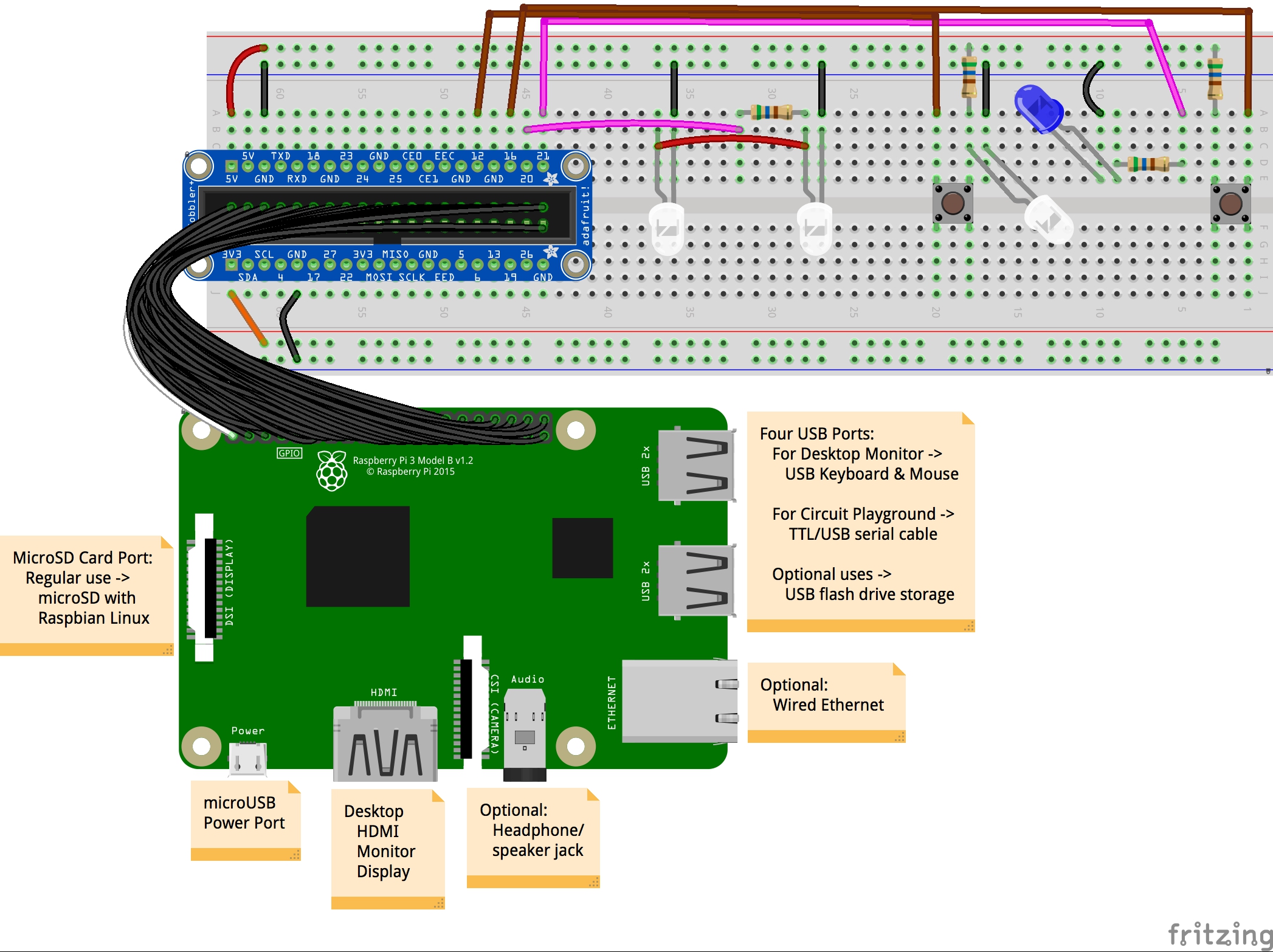
Beyond the ground, 5V, and 3.3V pins on the of the Raspberry Pi, we have a wide range of other pins we can tap into, as can be seen in the image below. Those labeled with a pound (#) sign, are especially prioritized to serve as inputs and outputs within programs. But how they are used is open to the decision of coders.
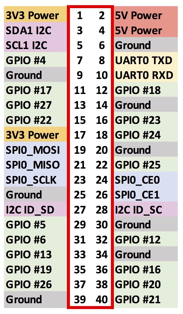
For this exercise, we’ll use GPIO #12 and GPIO #16 for the momentary switches and GPIO #20 and #21 for the LEDs to be integrated into programming code. The key reasons behind these choices include:
- They are placed on the side opposite to where the ribbon cable leans, improving visibility of the Cobbler labels.
- They are close to the electronic components.
- This pairs the switches (#12 and #16) and LEDs (#20 and #21) in the same ordering (#12 and #20 on the “white LED system” closer to the GPIO; #16 and #21 on the “blue LED system” further from the GPIO).
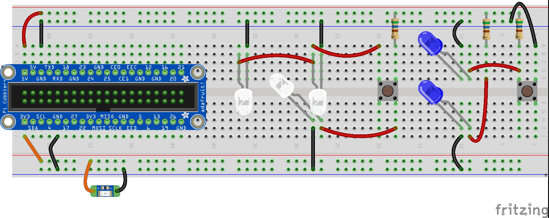
Part 1: Steps to Rewire the Circuits
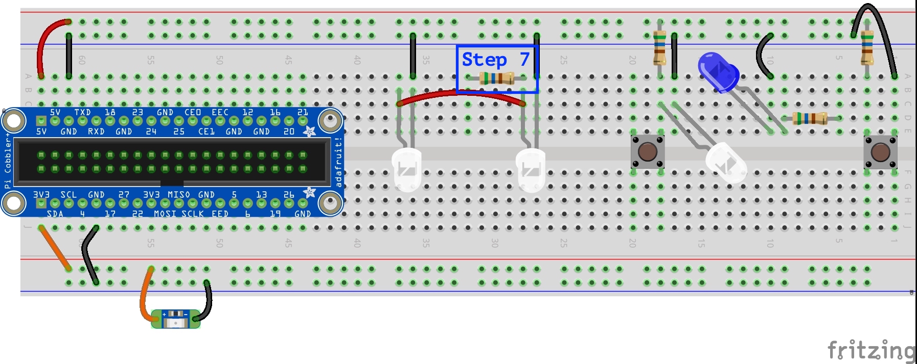
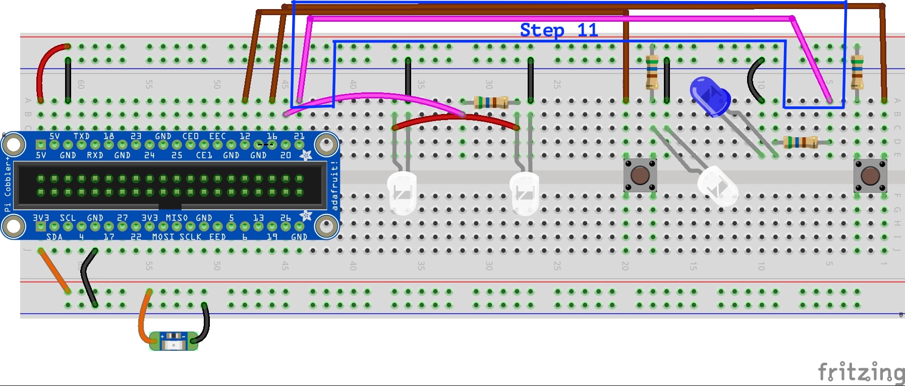
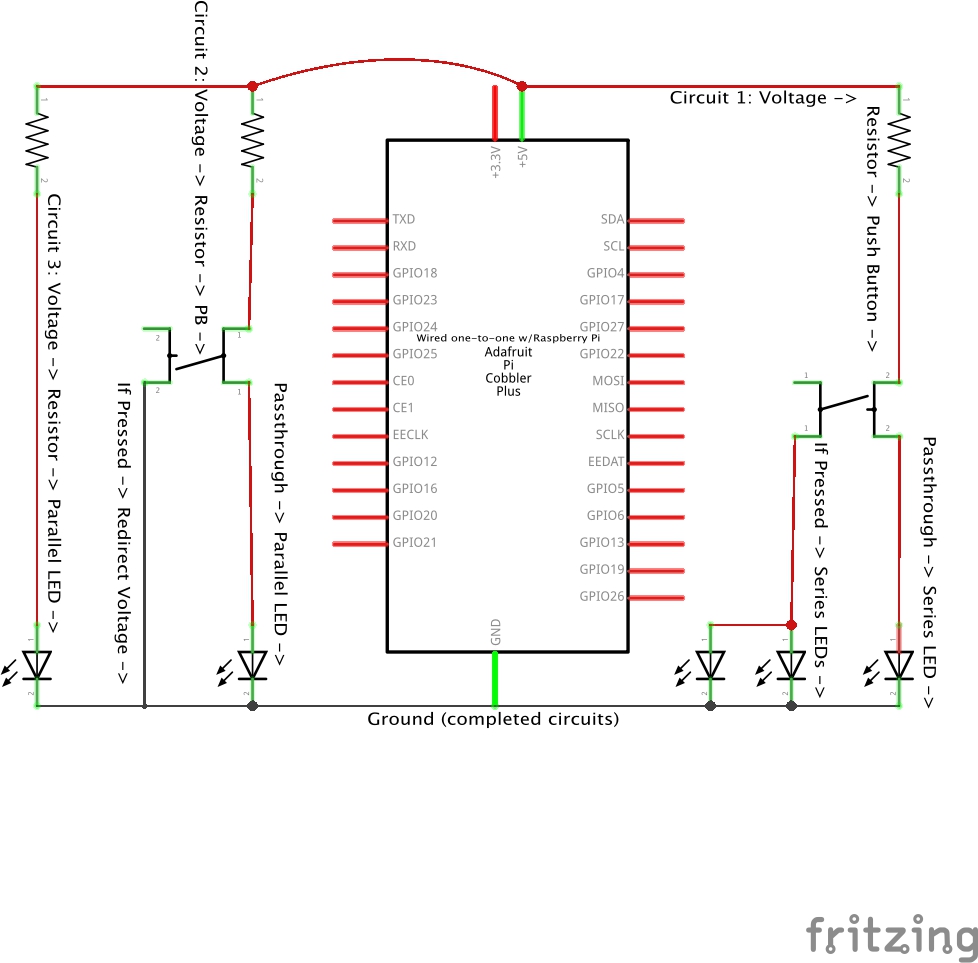
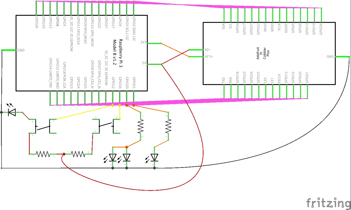
Here’s the configuration of our current circuits as a reminder of where we’re starting.[1]
- Remove the lower blue 10mm LED from row I, columns 9 and 10.
Also remove the ground and 5 volt jumper wires and the 560 Ω resistor for this LED.
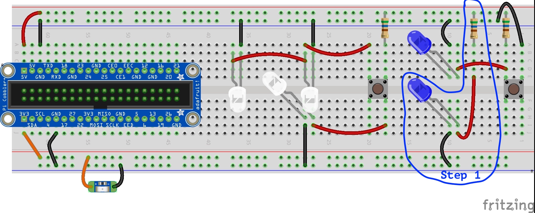
- Leave the upper blue 10mm LED in place along with the ground jumper wire.
But remove the 5 volt jumper wire from row D, columns 3 and 9.
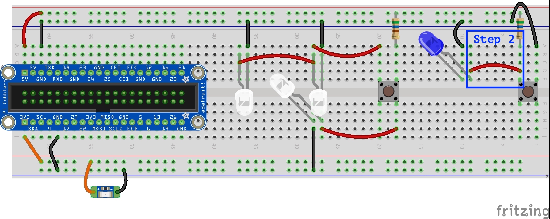
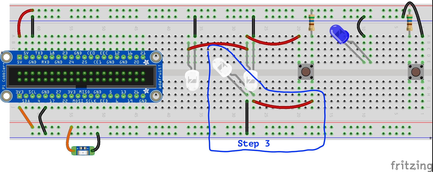
- Remove the lower white 3mm LED from row H, columns 27 and 28.
Also remove the ground and 5 volt jumper wires for this LED.
- Leave the upper white 3mm LEDs in place along with the ground jumper wires.
But remove the 5 volt jumper wire from row A, columns 20 and 28.
- Place a ground jumper wire from the upper blue rail to column 17, row A.
Place a white 3mm LED into row C, with the cathode leg in column 17 and the anode leg in column 18.
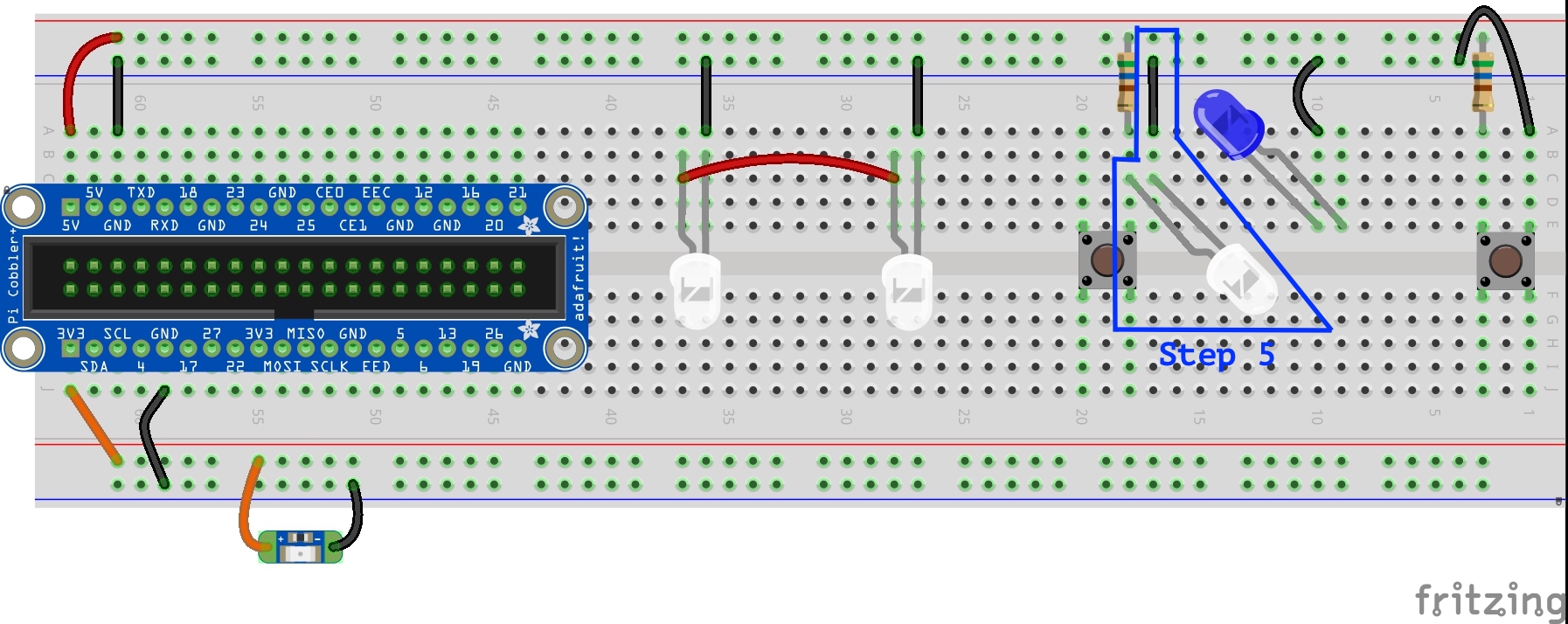
- Place a 560 Ω resistor in row D between columns 5 and 9, the anode leg of the blue 10mm LED.
- Place a 560 Ω resistor in row A between columns 28, the anode leg of one of the white 3mm LEDs, and column 32.
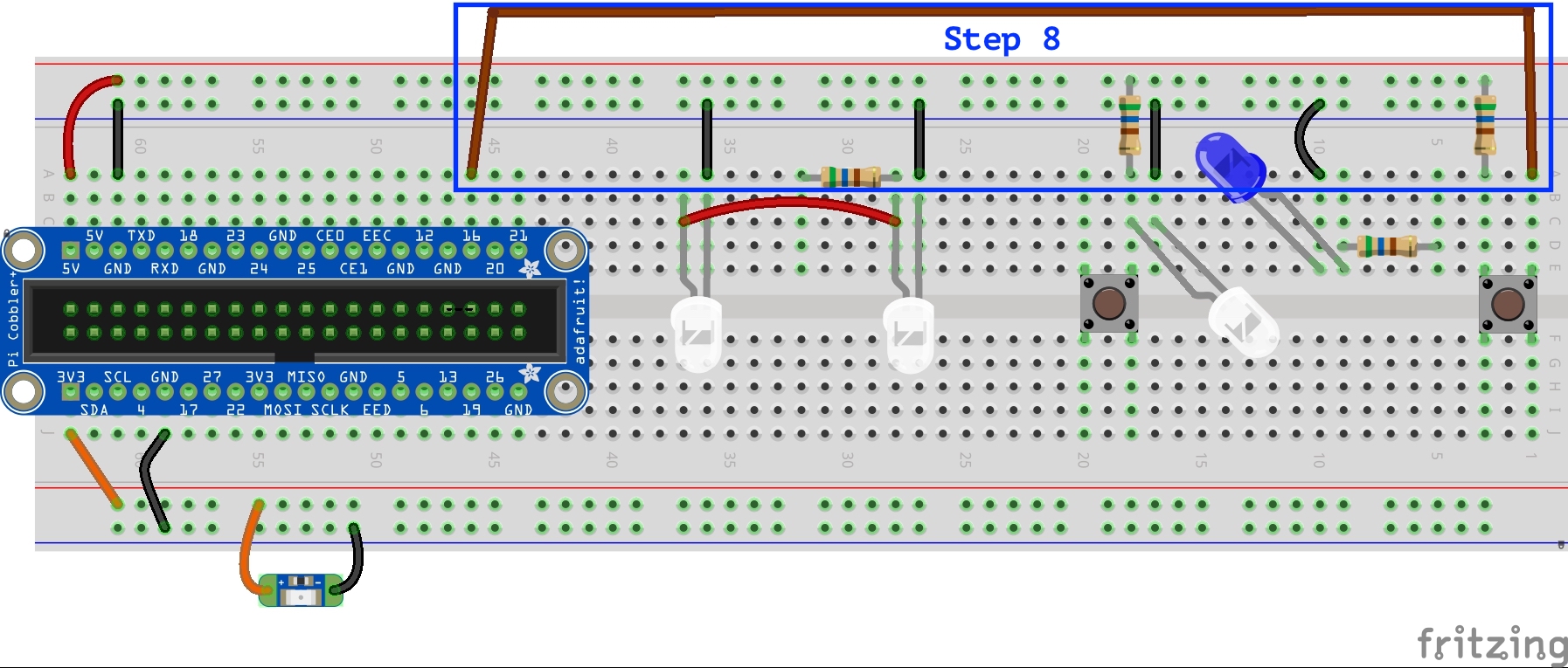
- Establish a connection between #16 of the GPIO and the right momentary switch.
To do this, leave the ground jumper wire for the right momentary switch connected to column 1, row A. But connect the other end of the jumper wire to column 46, row A.
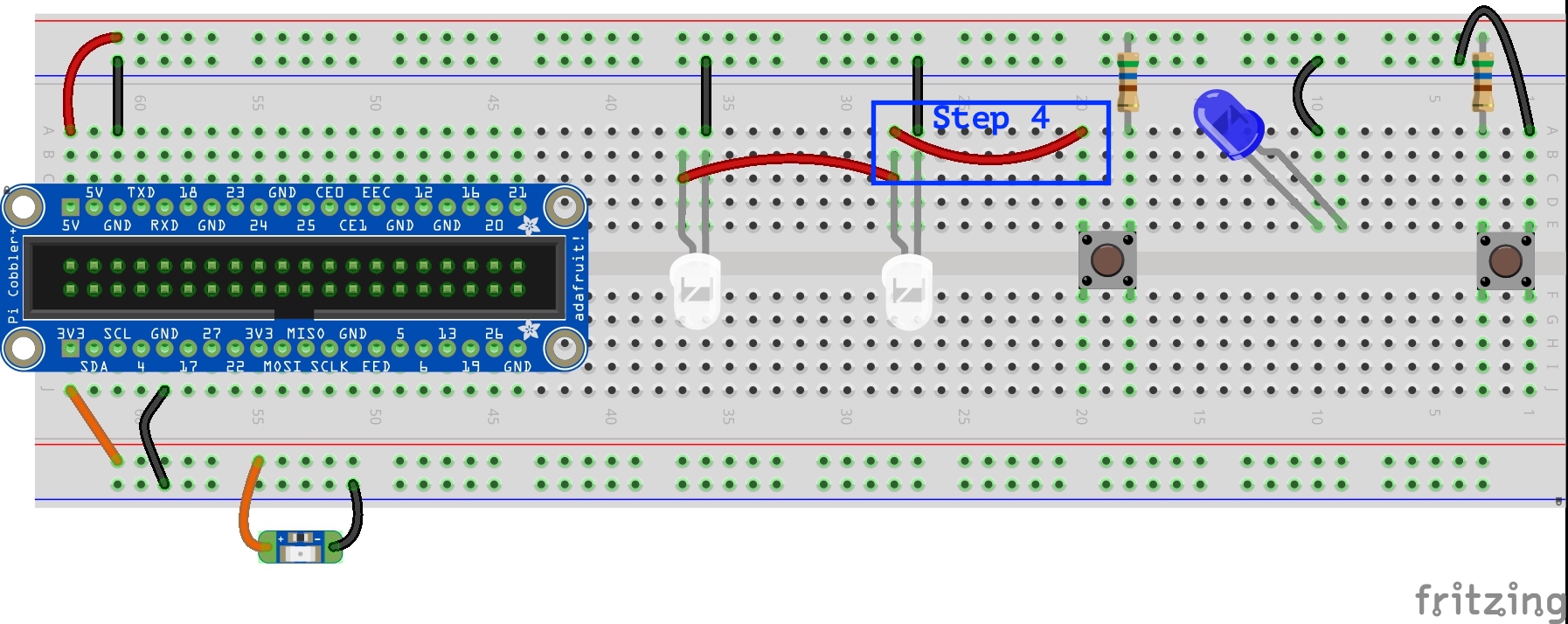
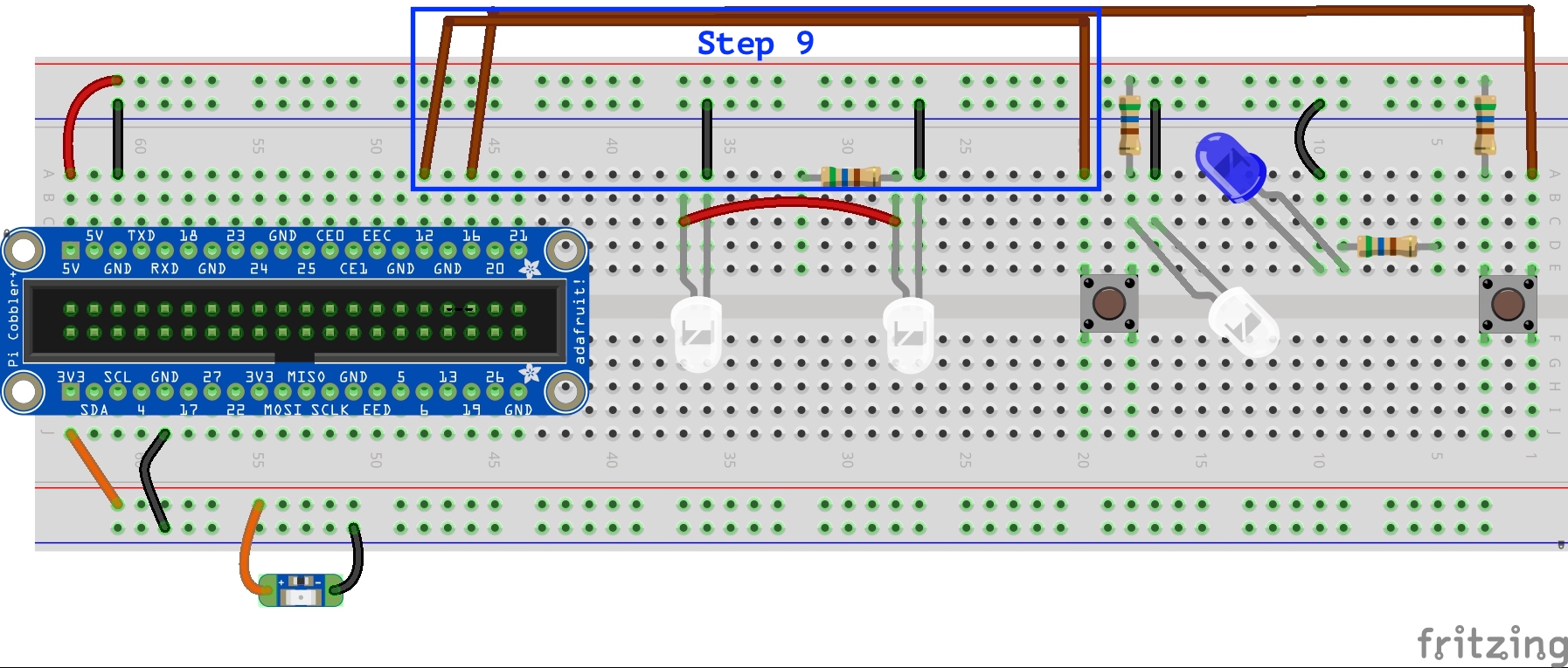
- Establish a connection between #12 of the GPIO and the left momentary switch.
To do this, run a jumper wire from column 20, row A to column 48, row A.
- Establish a connection between #20 of the GPIO and the white 3mm LEDs.
To do this, run a jumper wire from column 32, row B to column 45, row B.
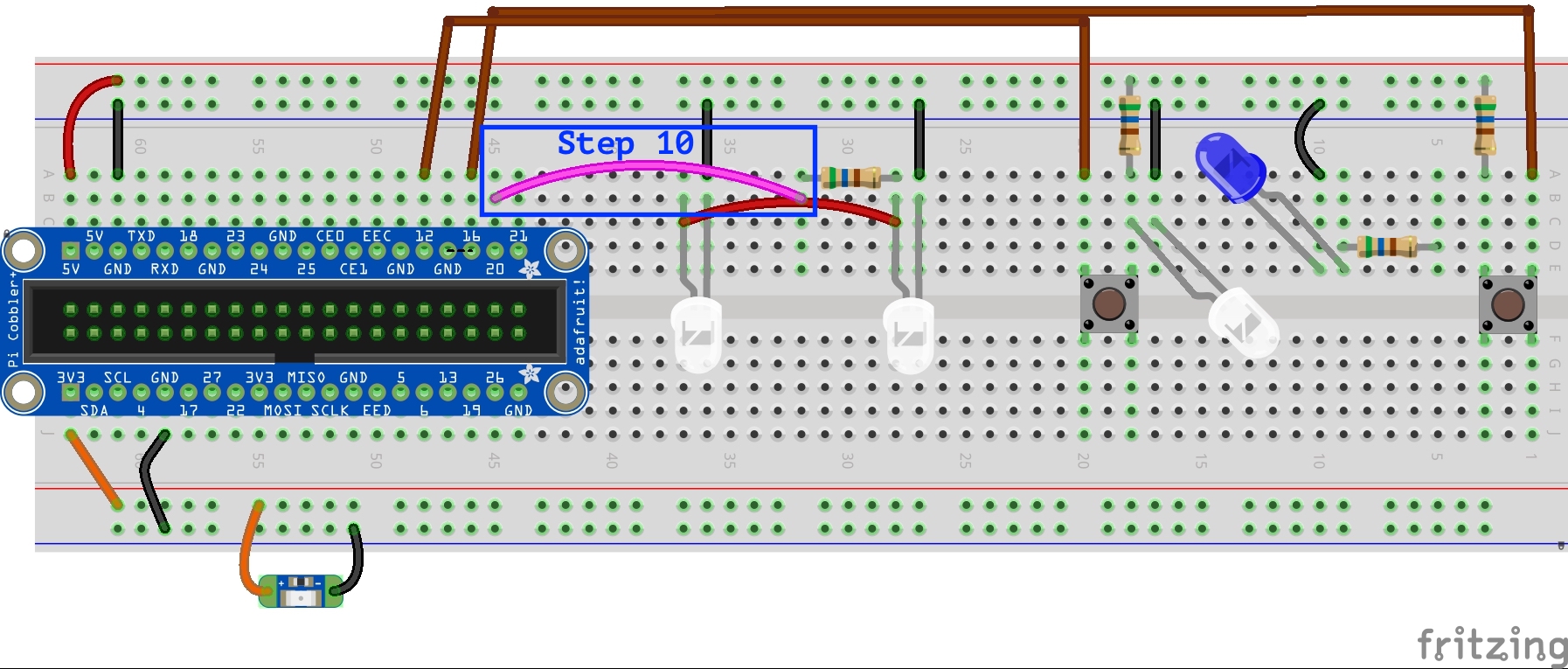
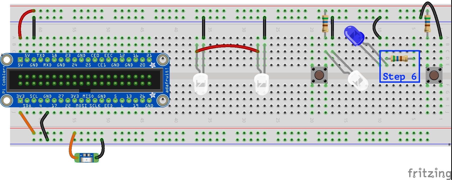
- Establish a connection between #21 of the GPIO and the blue 10mm LED.
To do this, run a jumper wire from column 5, row A to column 44, row A.
Part 2: Steps to Run the Code
At this stage, the exercise will vary based the adventure method you chose, Quickstart or Headless, to configure your Raspberry Pi. For this step, jump to your corresponding exercise below:
Quickstart
With our circuits complete, we are set to use software to determine whether or not the momentary switches connected to GPIO pins #12 and #16 are pressed or not pressed. We can then use that software to also determine whether to provide current to the LEDs connected to GPIO pins #20 and #21.
Take 7 minutes to watch the following video, then follow the steps below.
- Open the Chromium Web Browser.
- In the browser location tab, enter: https://uofi.box.com/s/i41htorftqpwnpmhoyd6dh6hjyrwjckl to open the Python file pushButton.py
- Take a glance at the code, but most importantly right click in the window to save the program as
pushButton.py(NOT as pushButton.txt as automatically listed on many computers). - Open a terminal window.
- At the command line, type:
python3 Downloads/pushButton.py
- Follow the printed instructions to turn LEDs on and off, and to exit the program when done.
Headless
Here’s how to use the console to set up and run Python code on your Raspberry Pi. This assumes that you have already connected your Raspberry Pi to your laptop using the USB to TTL cable and you have used the terminal (on Mac) or PuTTY (on Windows) to access the Raspberry Pi’s Command Line Interface remotely. If you need a refresher, Option 2: Headless Guide in Orange Unit “4C: Getting Started with the Raspberry Pi” provides detailed instructions.
- On your laptop, navigate to an internet browser. In the web browser, enter: https://uofi.box.com/s/i41htorftqpwnpmhoyd6dh6hjyrwjckl
- Briefly skim through the code.
- Select-all and copy the code.
- Navigate to the terminal window which is connected to the Raspberry Pi, type:
nano pushButton.py - This will create a new Python file on the Raspberry Pi called pushButton and opens the text editor Nano. Paste the copied code into Nano.
- To save your file and exit the text editor, type ^O (CTRL+O) then ^X (CTRL+X).
- To run your Python code, in terminal window, type:
python3 pushButton.py
Key Takeaways
Take 10 minutes to watch through this “Crash Course Computer Science” video from Carrie Anne Philbin highlighting how “Instructions and Programs” can serve as a first step from hardware into software.
In previous sessions of the Orange Unit, circuits were constructed using electronic components without code.
Within these circuits, we could have used the breadboard with a wide range of current and ground sources to the Cobbler beyond just the Raspberry Pi power source.
As mentioned at the start of this activity, we chose to use the Raspberry Pi GPIO #12 and GPIO #16 to read the state of the momentary switches, and GPIO #20 and #21 control the state of the LEDs. In this case, the Raspberry Pi’s GPIO and associated electronics and embedded code together create one, more complex circuit. Code, in this case using the Python programming language, is used to determine the activities based on the state of the momentary switches and the design decisions controlling the state of the LEDs.
The key reasons behind these choices included:
- They are placed on the side opposite to where the ribbon cable leans, improving visibility of the Cobbler labels.
- They are close to the electronic components.
- This pairs the switches (#12 and #16) and LEDs (#20 and #21) in the same ordering (#12 and #20 on the “white LED system” closer to the GPIO; #16 and #21 on the “blue LED system” further from the GPIO).
How might you have designed it differently?
True or false? As we move from circuits made exclusively of physical electronic parts to ones that also include programming code, greater opportunities for innovation-in-use become available.
Exercise: Playing Counterstories Saved to the Raspberry Pi
While we may already have used an application on our personal computers to play our counterstories, let’s see what it might be like to use the Raspberry Pi microcomputer to do this instead. Later in the book, we’ll move to using the Circuit Playground Express to play selected stories. And then we will install an Apache web server onto the Raspberry Pi so that we can play them via a web page as well. But first, let’s get to the point of copying files to the Raspberry Pi and playing the audio using the OMXPlayer application found on the Raspberry Pi.
As part of this exercise we’ll take the following steps:
STEP 1: Establish a counterstory workspace on your laptop. This folder will be used to clearly identify multimedia data that will be transferred to and from the Raspberry Pi as needed. Copy this folder to a USB flash drive.
STEP 2: Transfer data files between your laptop and the Raspberry Pi using a USB flash drive.
STEP 3: Test the audio playback on the Raspberry Pi. While there are many ways to play audio and video using the Raspberry Pi, we will opt for the built-in OMXPlayer.
Step 1: Establish a Counterstory Workspace on Your Laptop
On your laptop, set up the digital counterstory components:
- Create a folder called “cstories” to store counterstory MP3 files.
- Save one or more counterstory drafts as MP3 files in your cstories folder.
- Grab a USB flash drive and insert it into your laptop.
- Copy the cstories folder and its contents to the USB drive.
Step 2: Transfer Files From Your Laptop to Your Raspberry Pi
- Establish a Raspberry Pi terminal window. Once you have your terminal window open, the steps that follow are exactly the same.
- PATH 1: If you have a keyboard, monitor, and mouse connection with your Raspberry Pi, use the start tab to open a new terminal window.
- PATH 2: If you are running the Raspberry Pi headless (that is, without a keyboard, monitor, and mouse), use the TTL/USB Serial Cable to connect the Raspberry Pi to your computer. (Jump back to last session if you need a refresher!)
- In this case we see the “~” that indicates we’re in the home directory. For practice we’ll first make sure we’re in the home directory of user “pi” by using the command “cd” to change to the “~”, or user’s, home directory:
pi@raspberrypi:~ $ cd ~
pi@raspberrypi:~ $ - Insert the USB flash drive into a USB port on the Raspberry Pi.
- Next, we need to learn the name of the USB flash drive. Enter this command, which shows all of the attached “drives” (like boot) and their available disk space on a human-readable format. Note that commands are case sensitive.
pi@raspberrypi:~ $ df -H - Look under the “Filesystem” column for the row which begins
/dev/sda. The name of the USB drive will be in the “Mounted on” column, following/media/pi.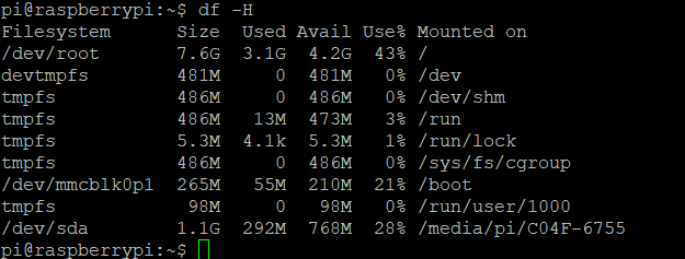
- Once you know the name of the USB drive, you can copy the cstories folder and its contents from the drive to your Raspberry Pi’s home directory. In the following command, replace the name of the USB flash drive with your own.
pi@raspberrypi:~ $ cp –r /media/pi/NameOfUSBdrive/cstories ~/cstories/
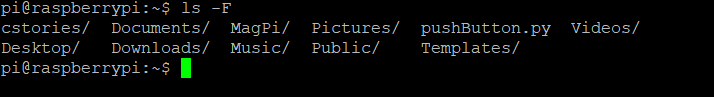
Note there is a single space between/cstoriesand~/cstories/. - If it seems like nothing happens after you run the command, that’s because it worked! Enter
ls –Fto list the contents of your home directory, indicating the folders with a forward slash at the end. Hopefully, you will see thecstories/folder listed! Stay logged in to your Raspberry Pi terminal as we will come back to this in a minute.
An introduction to the terminal window can be found in the end notes of the book: Using the Unix Command Line.
Step 3: Testing the MP3 Audio Playback on the Raspberry Pi
OMXPlayer is an audio and video player made specifically for the Raspberry Pi. It comes pre-installed on the Raspberry Pi OS. We’ll be using this as our digital Little Free Library tool. For more on the capabilities of OMXPlayer and instructions on its many user commands, visit the OMXPlayer website.
To test the audio playback of the Raspberry Pi:
- Connect a headphone or speaker to the audio jack on the Raspberry Pi.
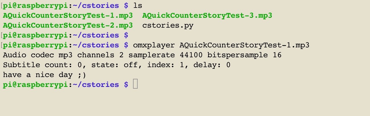
- Go back to your Raspberry Pi terminal window. Move into the cstories/ folder, also called changing directories, and then list your MP3 files, with the following commands:
pi@raspberrypi:~ $ cd cstories
pi@raspberrypi:~ $ ls
- Run OMXPlayer for one of the MP3 files you copied over from your laptop. For instance, if your MP3 file is called
AQuickCounterStoryTest-1.mp3, enter:
pi@raspberrypi:~/cstories$ omxplayer AQuickCounterStoryTest-1.mp3 - If you are connected to an HDMI monitor and don’t hear any sound, try adding
-o localbefore your MP3 file name. This will ensure the sound plays over the audio port, instead of the HDMI port.
Wrap Up
We’ve gone from basic LED circuits in parallel using different levels of resistance and different voltages, to LEDs in series controlled by momentary switches, to integrated circuits, to code-based circuits. We have also taken our first dips into the Raspberry Pi microcomputer pond to see how these electronic parts, along with a range of other electronics, come together to create large, complex systems like computers.
A wide range of individual electronic components can be brought together using power and ground sources and conductors to build individual circuits, like the three different LED circuits we created. Using a printed circuit board, these electronic components can be put together to create an integrated circuit, like the Sequin LED integrated circuit. Integrated circuits and additional electronic components can be further put together with code to create limited purpose microcontrollers like the Circuit Playground Express we’ll use in the Blue Unit, and general purpose microcomputers like the Raspberry Pi.
As mentioned in a video segment at the beginning of this session, my history with computers goes back to the mid-1970s in junior high, and my work with general electronics even longer, as I grew up in my family’s sawmill. In this next video, I share my memories of electronics and programming during the late 1980s and early 1990s as I worked on my research as a PhD student at Rutgers. You may find some similarities to the work we’ve just done!
Comprehension Check
- Fritzing breadboard graphics are licensed under CC-BY-SA 3.0. ↵
A general purpose input/output, or GPIO, is a common, open-ended transmission mechanism used with integrated circuits on microcontrollers, microcomputers, and other printed circuit board electronics. Pins are provided to which female-ended wires can be connected. GPIO pins can be programmed as input (e.g., sensor data; ground) or output (e.g., state change; power) sources. GPIO pins can be preconfigured for special purposes, or can remain undefined until specified by a user at run time. In general, GPIO provides a means to tailor pins to fit specific design goals within applications, as well as reusability across applications.
Electrical sensors are devices used to detect input from the physical environment. Light sensors might automatically turn on the headlights of your car, while heat and chemical sensors might turn on a fire alarm. And motion sensors might turn up the heating or cooling in a house, or might count how many people have passed through a gate to and from a library. The Circuit Playground Express that comes with the toolkit has a range of sensor inputs within this printed circuit board, including:
Analog light sensor to detect ambient light, with similar spectral response to the human eye.
Temperature sensor calculated using the analog voltage at a given moment.
Microphone audio sensor is a digital microphone that works similarly to the microphones built into our laptops and smartphones, but is smaller and less expensive, well-suited for this educational microcontroller.
Motion sensor using an accelerometer, detecting both motion and gravitational pull.
Seven capacitive touch sensors that can sense the touch of a person, human or otherwise.
