


Orange Unit: A Person-Centered Launch
1B: Introduction to Electronic Circuits
Background Knowledge Probe
Write a list of the electronics that you make use of on a regular basis.
- Who comes to mind as the designers of these?
- What parts, inside and outside the hood, were used to build each one? To use it?
- What have you done with any items that started to work less than optimally?
Technical Introduction
Example: A Single LED Circuit
An electrical is a path in which electrons flow from source to ground. The source is usually measured in (the force, expressed in volts) or (the flow, expressed in amps). A (expressed in ohms) controls the flow of this source.
When I water my garden from a rain barrel, a full barrel has more pressure than one that is almost empty. That full barrel is the equivalent of a higher voltage , for instance, one that is 240 volts. A barrel two-thirds of the way full may be more like a 120 volt power source, while a nearly empty rain barrel may be closer to a 5 volt power source.
If I have a spray nozzle hooked up to my rain barrel, I can often use a lever to increase or decrease the water’s flow. This is equivalent to the current of the power source. Some of my water hoses are 1/2″ thick, while some are 3/4″ thick. This is equivalent to bigger or smaller ohms of a resistor, respectively, since a thinner hose increases the resistance of the flow of water compared to the thicker hose.
As a side note, in electrical engineering, provides a basic equation I=V/R. This states that current (I) is equal to voltage (V) divided by resistance (R). And as all Trekkies know from their days with Jean-Luc Picard, resistance is not futile, it’s essential! Beyond this, don’t worry if you are ready to put aside these particular details.
are commonly used to draw out the path used by the electronic components to complete a circuit.
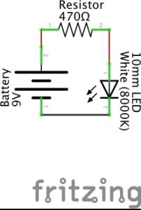
As an example, the Fritzing image above is a schematic with three electronic components:
- a battery
- a resistor
- a
The lines between are not electronic components, but rather are some form of conductive material like a metal wire that is used to carry the current from component to component. In the schematic, a positive current leaves the 9 volt battery and passes through a 560 ohm resistor before connecting to the positive charge of a 10mm white LED. From there, it passes through the negatively charged leg of the LED to the ground connection of the 9 volt battery, completing the circuit. Only when this circuit is fully and properly completed and the battery has sufficient charge to dispatch a current will the LED turn on. (Schematics and diagrams in this book were primarily created using the open source program Fritzing.)[1]
Schematics don’t tell us anything about how the circuit is actually built, and indeed the visuals for the different components needed are confusing artwork until their interpretation is provided. But with a little bit of practice, schematics become a unique conceptual information source. We can use design thinking and rapid prototyping to physically make the circuit using specific parts on hand or acquired to achieve something we value, even if it’s just good enough to help more than bother us.
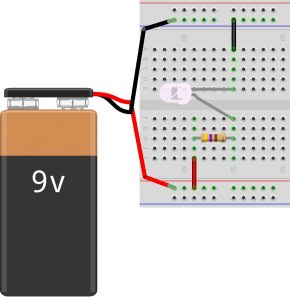
Often times, when you look for a plan or pattern to use electronics to perform a certain task, instead of a schematic, you’ll find a physical diagram of the parts as demonstrated in the Fritzing image shown above. This diagram is based on someone’s layout choices using available components to actually implement the circuit drawn in the Fritzing schematic at the start of this example. In the physical diagram, we see electrical components connected using a solderless , a plastic board with conductive clips under groupings of plastic holes, thereby allowing the passage of current between components.
At the left of this particular diagram, a red wire brings the positive current of the battery to the lower red rail of the breadboard. Another red wire moves it from this rail to row J, column 59. Row H, column 59 then connects the current to one leg of a 470 ohm resistor, which carries that current, now under resistance, to row H, column 55. This brings the current to the positive charge of a 10mm white LED. Row E, column 55 is connected to the negatively charged leg of the LED, which then passes to row A, column 55 where it is connected to a black wire that carries the current to the upper blue rail on the breadboard. A black wire then brings the current to the ground connection of the 9 volt battery, completing the circuit.
As you move forward, you may find yourself exploring and evaluating a variety of online guides, resources, and examples and comparing them to what is shown in the book. (Indeed, take a deep dive through the many examples found at Adafruit Learning System, from which we draw many for this book, for an extraordinarily wide range of electronic systems, along with supporting code.) Sometimes you may find schematics. But more often you’ll find diagrams illustrating how someone or a group have put the circuit into practice. Know that diagrams may be rigid as they tend to focus on a specific task in a specific configuration in a specific environment that suits a specific cohort, community, or culture. Schematics, on the other hand, are found in more professional settings and as such can be applied to a greater range of applications. These schematics, after doing research to define the components illustrated using specific visualizations, will also prove very helpful for problem solving or rapid prototyping for all innovators, regardless of experience.
It may be helpful to think of schematics as standards used for many different applications, projects, and occupations. Schematic drawings are relevant for many users from electrical engineers to K-12 students. For example, circuits and schematics are part of the Next Generation Science Standards (NGSS) Energy Unit for elementary school students in grade 4.[2]
Underneath the Hood of the Breadboard
A solderless breadboard is a plastic board used to create models or prototypes of an electric circuit. They’re solderless because you can easily push wires into the provided holes and later pull them out to move them into new configurations. They come in different shapes and sizes. The most commonly used “full sized” breadboard is 6 1/2″ long and 2 1/8″ wide.
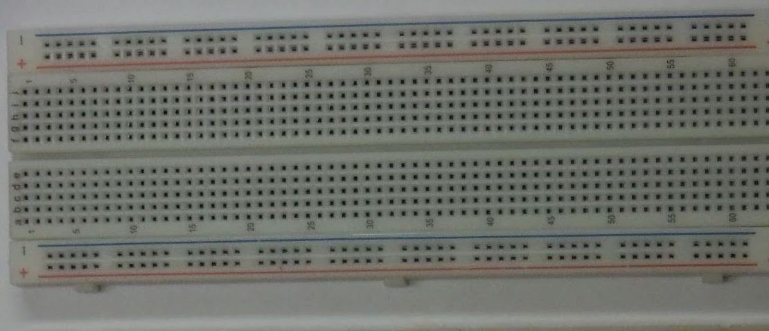
Below, you’ll note several different images of a full sized breadboard. In the first image, you see the typical working view of the breadboard.
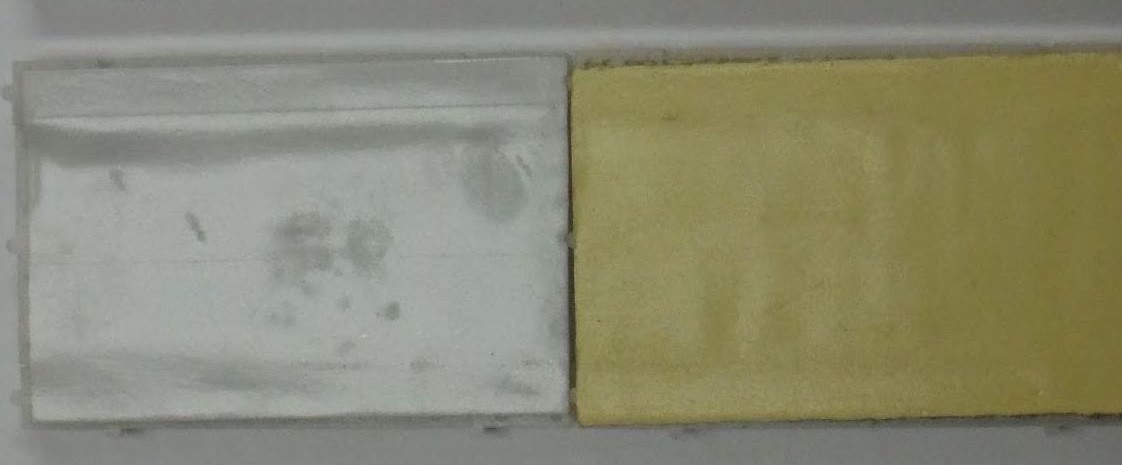
In the next image, we see the bottom side of a breadboard. The left half of the center image has the sticky covering revealed, while the right half has the protective covering installed. If the breadboard is moved around a table or desk, a protective covering remains on the underside of the breadboard (seen in the right half of the center breadboard). You can remove that covering to enable the breadboard to stick to a surface (seen in the left half of the center breadboard).
In the breadboard image below, we see the underside of a breadboard, but this time with the sticky tape fully removed. Breadboards typically come with rails along the edges, with conductive metal clips (two of which are shown at the very bottom of the image) installed so as to carry the flow of current along the extent of each rail.
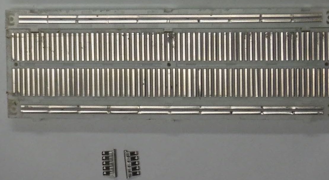
If you compare this image of the breadboard metal clips to the image of the top side of a breadboard, you’ll note there’s a red colored rail and a blue colored rail on the upper part, and another red rail and blue rail on the lower part of the breadboard. The red rail is typically used to carry a positive source to a circuit or series of circuits, while the blue rail is typically used to carry the circuit or series of circuits to ground. The main part of the breadboard connects together groupings of five holes using 126 conductive metal clips.
Thus, column 1, row A is connected to rows B, C, D, and E of column 1 with one metal clip. Column 1, rows F, G, H, I, and J are interconnected with a second metal clip. Column 1, rows A, B, C, D, and E do NOT connect with column 1, rows F, G, H, I, and J by default. They will only interconnect if a wire or electronic component is plugged into one of the left holes of column 1 and also to one of the right holes of column 1, and is set to pass a current from one connection to the other.
Building Our First LED Circuit Using the Raspberry Pi Electronics Toolkit
In the previous example, a circuit was created using a 9V battery, as shown in both a schematic and a diagram. Throughout the rest of this book, we will typically not use a battery to power our electronics. Instead, we will use a small, single-board called the Raspberry Pi as a power source. The Raspberry Pi actively used around the world both for initial design and ongoing application of networked information systems for use in the field. It connects to 120V (United States) or 240V (many other nations) electrical power from a wall outlet or other alternating current (AC) power source using the kit’s Micro USB cable. The Raspberry Pi converts this voltage into 5V and 3.3V power supplies that can be accessed using the pins of a Raspberry Pi. These pins provide a hardware link between the Raspberry Pi computer and electronics from the outside world.
For our prototyping activities, we’ll use a 40-pin ribbon cable to extend the GPIO pins to our breadboard by way of an Adafruit Industries assembled Pi breakout printed circuit board. This brings together the Raspberry Pi’s GPIO pins and the solderless breadboard, along with a label for each pin, using a single ribbon cable rather than 40 individual wires, to make “cobbling together” prototypes easier.
Exercise: Building and Testing an Electronics Prototyping Platform
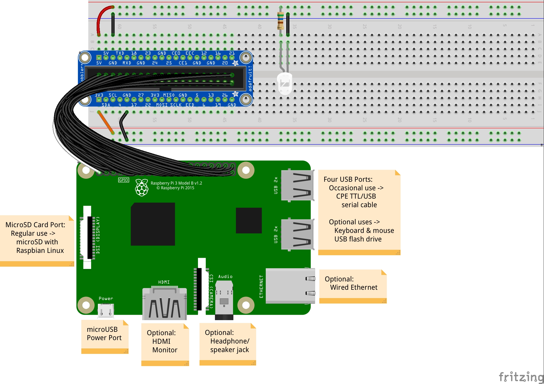
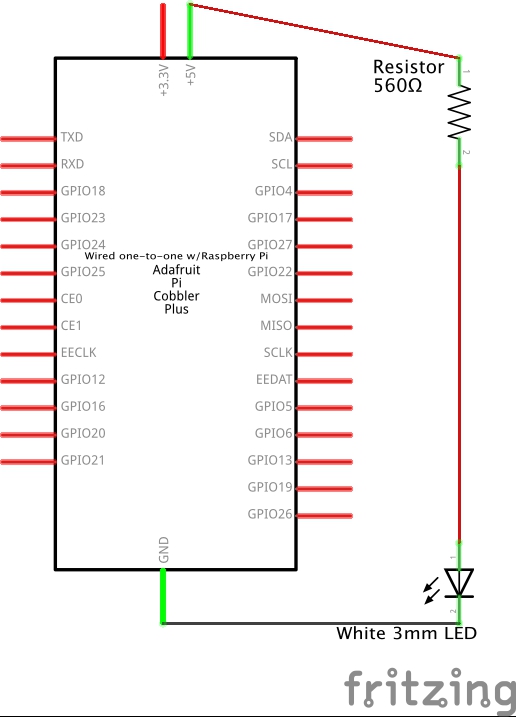
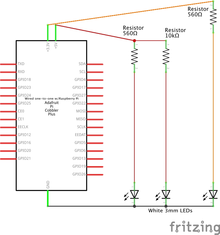
The image above provides a diagram of the basic configuration of the Raspberry Pi, GPIO ribbon cable, Cobbler, and breadboard. It also includes a diagram of a basic circuit in which 5 volts of current pass through an electronic component called a resistor, then through an electronic component called an LED, before returning to ground, thereby completing the circuit.
In the above diagram, it is important to note that there are only four electronic components illustrated:
- An unidentified larger black square microprocessor on the Raspberry Pi
- An unidentified smaller black square integrated circuit microprocessor on the Raspberry Pi
- A 560 Ω resistor
- A three millimeter (3mm) white LED on the breadboard
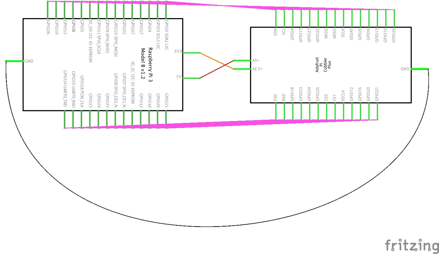
This can also be used using two different schematics:
- First, a schematic illustrating the conceptual layout of how the electronic components and power/ground sources on the Raspberry Pi connect to the Cobbler.
- Second, a schematic demonstrating a conceptual layout of how, using the Cobbler, a 5V (volt) power source can be connected to a 560 Ω (ohm) resistor electronic component, then to the positive, , leg of a Light Emitting Diode (LED), then from the negative, , leg of the LED to a ground source to complete the circuit, thereby creating a white light source.
Before moving on to the steps listed below, watch these video demonstrations for the hands-on process and description of parts.
Steps
Follow these steps to complete this exercise. You are highly encouraged to do this with one or two other people who are simultaneously working on their own toolkits. Other than the first step in which you are watching the video (“see once, do once” style), one person should do the work hands-on while the other(s) observe, work to identify yet/not yet moments, and do explorations to help facilitate failing forward. After the first person reaches a certain point as agreed upon by the collaborative, then the other(s) will work through those same steps with support from the first person. In this way, is implemented.
- Take out the needed parts from your toolbox.
- Connect the Cobbler to the breadboard, row D and H of column 63 to column 44.
- Connect the 40 pin conductive wire ribbon cable to the Cobbler, with the white wire connecting to the 3V3 pin, pin #1, on the Cobbler.
- Remove the clear cover of the Raspberry Pi case.
- Connect the other end of the 40 pin ribbon cable to the GPIO of the Raspberry Pi, with the white wire facing the shorter side at which the 3V3 pin #1 is placed.
- Connect a red male to male wire to the 5V pin attached to column 63. The red wire can be connected to either row A or B. Connect the other end to the nearby red rail.
- Connect a black male to male wire to the ground pin attached to column 61. The black wire can be connected to either row A or B. Connect the other end to the nearby blue rail.
- Connect an orange male to male wire to the 3V3 pin attached to column 63. The orange wire should be connected to row J. Connect the other end to the nearby red male.
- Connect a black male to male wire to the ground pin attached to column 59. The orange wire should be connected to row J. Connect the other end to the nearby blue rail.
- Replace the clear cover to the top of the Raspberry Pi case.
- Bend the longer leg of the LED so that it is even with the shorter leg.
- Connect the longer anode leg of the LED to column 37, row B, and the shorter cathode leg of the LED to column 36, row B.
- Take a blue male to male wire jumper wire. Connect one end to column 36, row A. Connect the other end to the blue ground rail.
- Tightly bend down the two legs of a 560 Ω resistor. The resistor should have green, then blue, then brown bands, and be followed by a gold tolerance band. Connect one leg of the 560 Ω resistor to the 5V red rail, and the other end to column 37, row A.
- Insert the Micro USB power cable to the Raspberry Pi. Insert the 120 volt or 240 volt side of the power cable to a proper source such as a wall outlet or extension cord.
- Confirm that the LED is properly lit. Use the troubleshooting guide in the next section to consider further steps.
Key Takeaways
In this exercise, we’ve entered into a first apprenticeship crafting a , using a Raspberry Pi microcomputer as a source for power and ground, and using a breadboard as the physical prototyping base tool. To do this, we brought together a number of wires, like the male to male and the 40-pin made of individual wires. In order to test this platform, we brought together two electronic components, a resistor and an LED, to provide some literal light on the platform.
In addition to these technical skills, we sought to bring in several socio-emotional skills development, including the ability to communicate and collaborate with others using a “see once, do once, teach once” strategy using pair/triplet programming, and potentially began exploring how failure serves as an essential step in project development, that is, a fail forward mindset.
There are many ways to design and build electronic artifacts. This can be done as individuals working to serve personal interests. This can be done as individuals working as experts to serve others broadly considered. This can be done as individuals working as experts to serve others more strategically. It can be done in groups randomly or strategically partnered to serve inwards or to serve outwards. It can be done as a community of practice in ways that include the contributions of a range of stakeholders. And it can be done in so many other ways as well.
- How did you work to do this first hands-on exercise of the book with electronics?
- How did I and others work to develop this exercise? How did it influence your work with electronics? Who else influenced your work?
- What makes an LED and a resistor electronic components? What makes wires, the Cobbler, and the breadboard conductors parts which support electronic components?
Troubleshooting Essentials
Design thinking leads us from inspiration to ideation to iteration and back. Iterations are typically done through picture drawings, models, and with electric prototypes, often through the use of breadboards. Failure is common, and generally remains the norm, from iteration to iteration for an extended period.
To positively fail forward, our iterations are an opportunity for us to discover how our inspirations and ideations aren’t aligning with our past and current iteration prototype. Said another way, iterations help us see how one part, much, or all of our design ideation is falling short of good enough. This helps inspire better ideations and sometimes even new inspirations, ultimately leading to better iterations — at least for us within the given testing context.
Let me say this again: Trying and failing is not optional. It is the norm. The general alternative to failing forward is failing to improve.
Accepting failure as a normal, active, ongoing part of what we do leads us to failing forward in ways that facilitate growth and betterment of ourselves, and when done across functional diversities and community cultural wealth, the betterment of others as well. In so doing, we foster a high performing community of practice.
So let’s assume the LED did not light up in the last exercise, or that it burned up in the last exercise, or that it won’t light up in the next exercise. Why not? What happened?
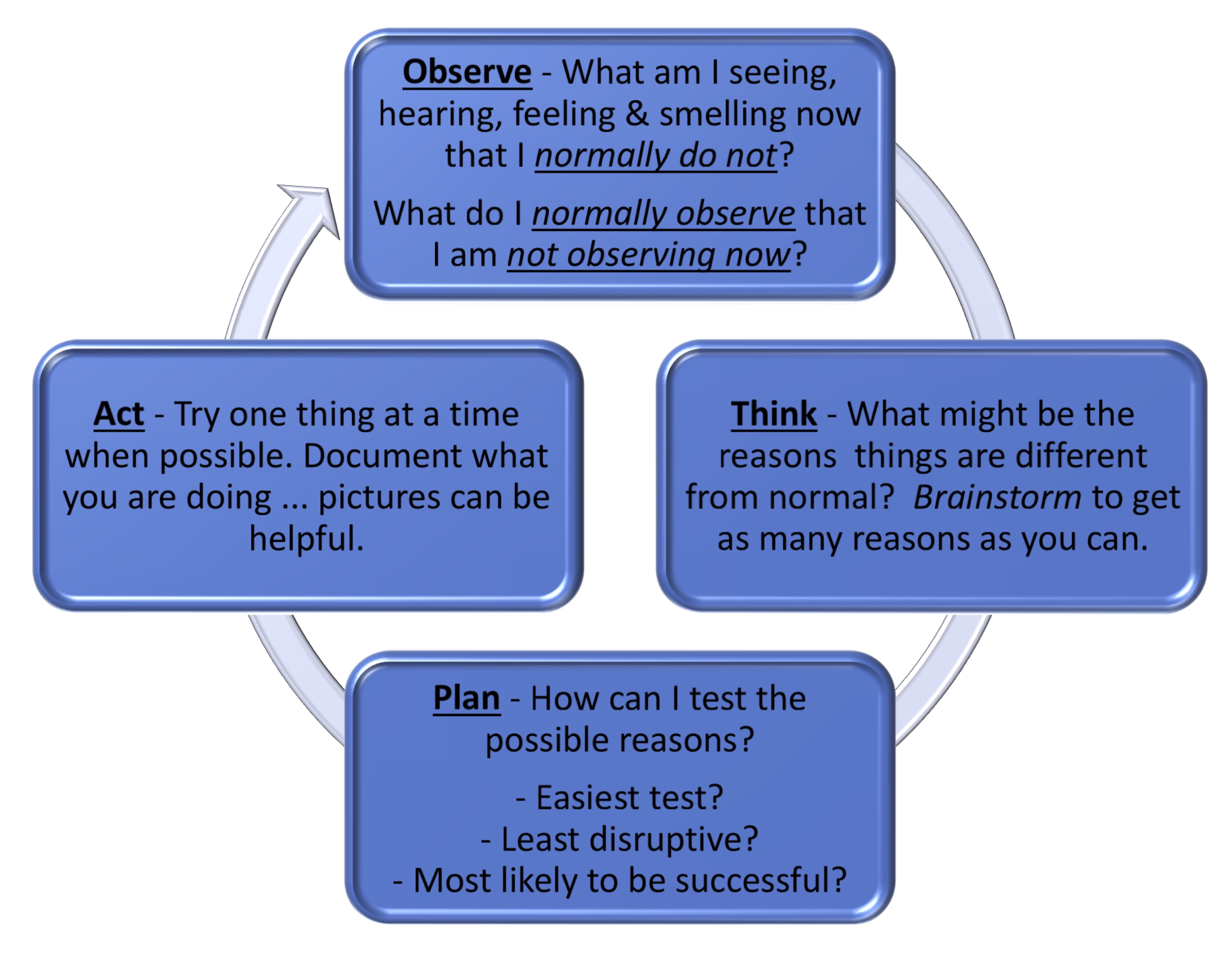
Humans and other more-than-human persons around us have a rich range of analog senses, such as sight, hearing, feeling, and smelling. These are a wonderful resource in the troubleshooting process. These analog senses provide a continuously variable physical quantity, such as the visible wavelengths of light. This stands in contrast to the digits 0 and 1 that typically represent the values of a physical quality provided by digital measurements.
Bringing our observations through those analog, continuously variable, senses into a process of critical thinking helps us create a plan for testing out a range of possibilities. Enacting that plan one step at a time helps us to continue the cycle of observation, thinking, planning, and acting. This is the heart and soul of inquiry-based learning as we collaborate in pairs and small groups through dialogue.
Throughout the remainder of the exercises in this book, and as you work through your own design activities putting your learning into practice, be sure to make extensive, preferably documented, use of these troubleshooting basics. It’s tempting to try it a few times and move on because troubleshooting the current exercises begins to become second nature. These experiences serve as a learning opportunity, but at the risk of having the learning become hidden knowledge that fails to fully help you as you encounter future problems.
Indeed, this is a reason why this book has been written using the Creative Commons Attribution-ShareAlike license. We hope you will add in annotations, page notes, and remixes for yourself and others to use as sources for their own design thinking projects. We hope the resulting inspirations, ideations, iterations, and failures support an advancing betterment of ourselves, those in our community of practice, and those we are serving through our creative works.
Do Something New!
For some, this is your first journey into electronic circuits. You’re Doing Something New through troubleshooting electronic circuits and failing forward!
For others, you may already have a lived experience with electronic circuits. This is not something new to you. But if you’re at all like me, some of this work has become rote, and the underlying terms, concepts, and principles hidden knowledge. For you, Doing Something New may be a work of re-remembering the codes to the electronic wheelhouse. And moving beyond, maybe its discovering some of the social influences that have shaped the non-neutral aspects of the otherwise strict laws of physics within.
For all, it’s likely at least some aspects of Collective Leadership, Community Inquiry, Action-Reflection, the Information Search Process, and Pair/Triplet Programming are new to you. Do Something New by incorporating one or two of these into your work this and every session individually and as part of your Community of Practice work.
Exercise: Two LED Circuits Using Different Ohm Resistors
In the last exercise, we used a 560 Ω resistor within our LED circuit. By providing a little to the passage of an electric current, we help to stay within the optimum upper and lower current flow boundaries of a designated LED. While some LEDs have greater tolerances to non-optimal current passing through, others have less. And most electric power sources have some increases and decreases of current within a given voltage depending on conditions in the moment. Resistors are an important means of balancing this out.
For most of our work, a 560 Ω resistor will be just fine. But for a later integrated circuit, we’ll use a 10,000 Ω (typically specified as 10k Ω) resistor. Let’s see how a 3mm diffused white LED with a 560 Ω resistor compares to one with a 10k Ω resistor conceptually.
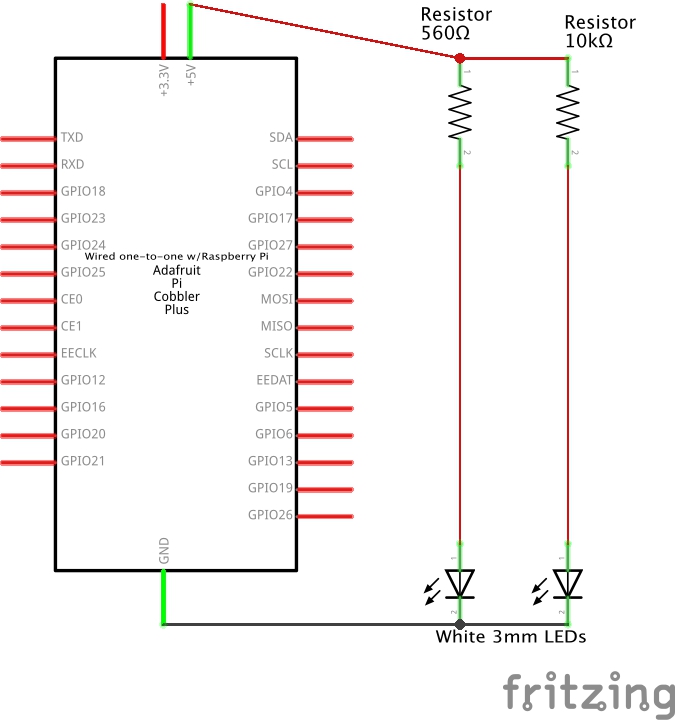
Each of the two LED circuits are designed as standalone circuits working in parallel. That is, if the metal wire from the 5V power source to the 560 Ω resistor were to somehow be cut, power would still flow over to the 10k Ω resistor – LED – ground circuit we’re about to build. Or vice versa if the wire to the 10k Ω resistor were cut and the 560 Ω resistor wire remained intact — the 560 Ω resistor – LED – ground circuit would remain live.
NOTE: Feel free to keep the Raspberry Pi plugged into the Raspberry Pi power supply. Also feel free to keep the first 3mm LED circuit live and the LED lit.
Before moving on to the steps, you are encouraged to do a “see once” viewing of the video in full.
Steps
You are again highly encouraged to do this with one or two other people as a pair/triplet programming exercise in which one is doing the hands-on while the other is reading through instructions, reviewing the work, and looking for additional resources in support of a fail-forward, growth mindset collaboration.
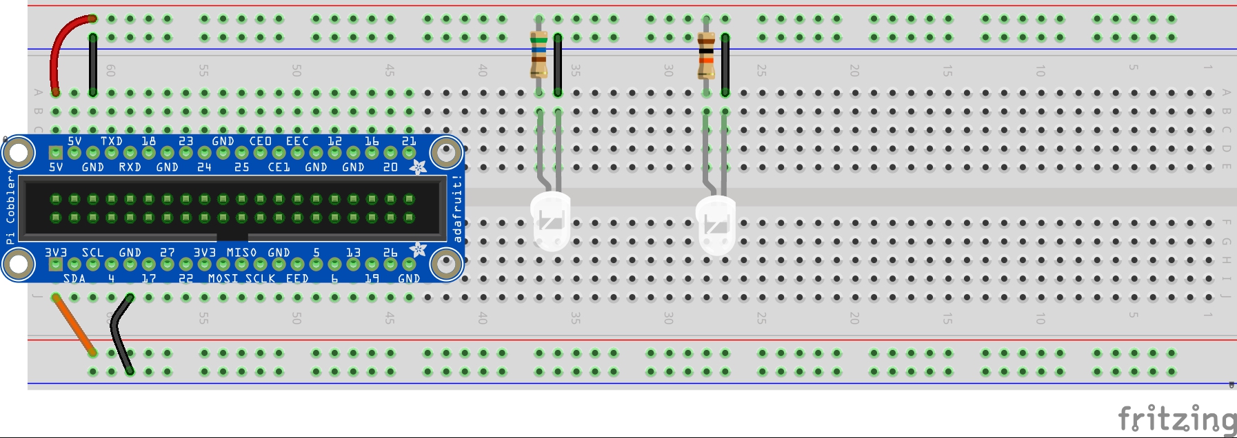
- Bend the longer anode leg of a second 3mm white LED to even out the length of the bottom side of the leg while also being able to identify this leg for the shorter cathode leg.
- Connect the longer anode leg of the LED to column 28, row B, and the shorter cathode leg of the LED to column 27, row B.
- Take a blue male to male wire. Connect one end to column 27, row A. This is the column associated with the cathode leg of the LED. Connect the other end to the blue ground rail.
- Find and tightly bend down the two legs of a 10K Ω resistor (it should be colored brown, black, and orange, followed by a gold tolerance band).
- Finally, connect one leg of the 10K Ω resistor to the 5V red rail, and the other end to column 28, row A.
- You should now see the LED turn bright, but it will be at a different brightness as compared to the one with the 560 Ω resistor. Let’s explore what we found, and some possible reasons why:
Key Takeaways
For this activity, a choice was made to locate the two LEDs 9 columns apart, but connected into the same rows. The same 5 volt power source was used running across the full of the upper red rail. The key difference was that the flow of current was changed by using two different Ohm resistors.
- Is the light coming from the two different LEDs the same, or different? If the same, why? If different, why?
- What are some reasons you can think of that we decided to position the LEDs, resistors, and wires in the way we did to setup your execution of this activity?
- What are some ways we might have done it differently, and in so doing may have created a better way for you to complete this activity?
Exercise: Comparing Differences in Resistance and Voltage
We’ve compared the brightness of LEDs using a 560 Ω resistor and a 10k Ω resistor. Now let’s test out the difference between a circuit using a 3.3 volt power source and a 560 Ω resistor and a circuit with our usual 5 volt power source.
Steps
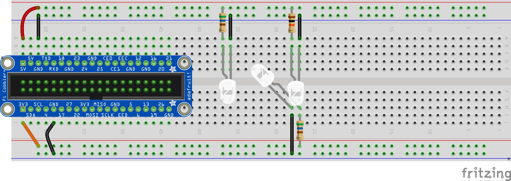
As shown in the conceptual schematic above, there will now be three standalone parallel circuits. Using the diagram below, implement the circuit shown in the schematic by adding a third white 3mm LED to row H, columns 18 (anode leg) and 19 (cathode leg). Connect a 560 Ω resistor to column 18, row I, and to the 3V3 red power rail. And finally, connect a 6″ male to male wire to column 19, row I, and to the lower blue ground rail.
Key Takeaways
For this activity, a choice was made to locate the two LEDs 9 columns apart, but connected into the same rows. The same 5 volt power source was used running across the full of the upper red rail. The key difference was that the flow of current was changed by using two different Ohm resistors.
- How is the brightness of this third LED different from the first two LEDs? What causes this difference, if any?
- What could you change to make the brightness of this LED the same as the first without relocating it on the breadboard? The second LED?
Wrap Up
This is just a first glimpse at electronic circuits and some ways we can work hands-on in design and prototyping of new circuits. There’s much more to come as we proceed through the Orange Unit and beyond. For now, take a few minutes to do a quick comprehension check on some of the key circuit terms and concepts we’ve used so far.
Comprehension Check
- Fritzing breadboard graphics are licensed under CC-BY-SA 3.0. ↵
- See Next Generation Science Standards’ 4-PS3 Energy for more examples. ↵
A semiconductor that passes current from one terminal to another terminal, and in which current can only flow in one direction. The kit used in this book includes a mix of different Light Emitting Diodes, or LEDs. Different LEDs work at different wavelengths (the measure of distance between the peak and the trough in a wave), associated with different recognized colors of light. Some LEDs are made to be especially bright, such as a car headlamp to help us see the road more clearly. Others are meant to be more diffuse, thereby working more as a source of information, like a car brake light or turn signal.
Small electronic switches allowing control of electrical flow within a circuit without using programming code.
When working with electrical components, a circuit is a complete, closed path that allows an electric current to flow. In this book, we work with active circuits that begin at a source voltage, pass through one or more electrical components, then end at the return, or ground.
A quantitative expression of the difference in charge between two points in an electrical field. The Raspberry Pi electronics kit provides both 5 volt and 3.3 volt sources for use in our circuits.
Current is a flow of electrons from relatively positive points to relatively negative points. Greater voltages have greater currents. As such, there is somewhat greater current when you use the 5 volt source of the Raspberry Pi than when you use the 3.3 volt source. Different electronics are capable of using different maximum currents, so it is sometimes necessary to provide resistance to reduce the current passing through the component.
Electrical resistance reduces the flow of current through a circuit. Resistors are the typical electrical component used to provide resistance in a circuit. The kit used in the book comes with five 560 ohm resistors, and five 10,000 ohm (or 10k ohm) resistors. In most cases, feel encouraged to work with the 560 Ω resistor.
Our homes, businesses, libraries, and other community spaces typically include wall outlets from which we can plug in our electronics. These are usually either installed to supply 120 volt or 240 volt alternating current (AC) power source to our devices. But many of our devices use a much lower voltage direct current (DC) power source. It is for this reason that we often need a power adapter that has a plug-in to connect to the wall outlet, and another that has another form of plugging, increasingly today a Micro USB connector, to your electronic device. For the kit used in this book, we use a power adapter that works with 110 to 240 volt AC power on one side, and provides 5 volt, 2.4 amp power via a Micro USB connector on the other side.
German scientist Georg Simon Ohm developed this simple, linear mathematical principle relating current (I), resistance (R), and voltage (V). There are three equations that are used in direct current circuits. If needed, these can help us to determine, for instance, which voltage source or which resistor ohms we should use to achieve a certain passage of current through our circuit.
V = IR ... Electrical voltage equals amperes times ohms
I = V/R ... Current amperes equals voltage divided by ohms
R = V/I ... Resistance ohms equals voltage divided by amperes
A symbolic and simplified diagram or other representation of a circuit. Throughout this book, schematics are used when an illustration of a circuit is needed without specifying exactly how these would be physically built using a breadboard or other prototyping platform. In this schematic illustration, we see the formal representation of the electronics used to create a complete and functioning circuit that include a 560 Ohm resistor, a 5mm LED circuit, and a battery. In the prototype illustration, we see one example of how this circuit could be constructed using a tiny breadboard and double-A battery.
A breadboard used to be a board (sometimes literally a board for cutting bread) with nails pounded into it so that you could wrap wires around them to make experimental models of electric circuits. Today, the breadboard is a piece of plastic with holes in it. Underneath each hole is a metal clip. These metal clips connect together a specified set of holes ordered into a row or column. This way, pushing a piece of conductive material into one hole right away connects that material to things pushed into other holes that are joined together by that clip.
A perfboard is a thin, rigid sheet with holes but no metal clips on the other side. Instead, copper pads are used, to which conductors can be soldered. In some cases, as with the perma-proto breadboards from Adafruit, copper is further used to group together certain holes, mimicking the breadboard in a way that provides greater durability for prototyping work.
An electronic device using a program of instructions to collect, store, process, and transmit data. Many of our daily use devices, including automobiles, mobile phones, home routers connecting a building's network to the wider Internet, the growing number of "smart" internet-connected devices like watches, building heating, ventilation, and air conditioning (HVAC), and light and sound systems, and our laptops and desktops are all built using computers. While some use a more significant combination of integrated circuit processors and potentially multiple printed circuit boards, increasingly these parts are more tightly integrated into a single printed circuit board and a reduced number of integrated circuits. Depending on design and use specifications and marketing, these may be referred to as microcomputers, microcontrollers, microprocessors, or System on a Chip (SoC). The Raspberry Pi is a general purpose microcomputer with integrated System on Chip central processor and other microprocessors.
A general purpose input/output, or GPIO, is a common, open-ended transmission mechanism used with integrated circuits on microcontrollers, microcomputers, and other printed circuit board electronics. Pins are provided to which female-ended wires can be connected. GPIO pins can be programmed as input (e.g., sensor data; ground) or output (e.g., state change; power) sources. GPIO pins can be preconfigured for special purposes, or can remain undefined until specified by a user at run time. In general, GPIO provides a means to tailor pins to fit specific design goals within applications, as well as reusability across applications.
A Cobbler, used in electronics in combination with a prototyping board such as a breadboard, is a plastic header to which a ribbon cable can be attached, which can then be inserted into the prototyping board. A T-cobbler extension is sometimes included using a printed circuit board, allowing the header to which the ribbon cable is attached to be separated from the male pins that are inserted into the breadboard. Labels on all cobblers identifying each of the electrical circuits associated with each pin can then also be included on the printed circuit board.
Integrated circuits (ICs) are semiconductor wafers which contain a collection of tiny resistors, capacitors, and transistors. These can then be built to serve a wide range of electronic functions. In practice, larger sized electronic components used to build circuits are first tested using materials like breadboards for rapid prototyping. They are then redesigned to be built into integrated circuits and optimized for regular, more standardized use. At times, a mix of electronic components along with integrated circuits are themselves used on breadboards to do further rapid prototyping of yet larger circuitry. The 5-Key Capacitive Touch Sensor included in the kit for this book contains a mix of integrated circuits. Examples of integrated circuits include: processors, memory, controllers.
The positively charged electrodes conducting electric current from a cell into a device like a diode.
The negatively charged electrodes conducting electric current out of a device like a diode and back to a cell.
Pair programming (or triplet programming) is common in software development. Two (or three) programmers collaborate on design, coding, and testing, with qualitative evidence suggesting the subsequent design is better, resulting in simpler code that is easier to extend. Further, whether the pair programming occurs between two novice programmers, between a novice programmer and a more experienced programmer, or between two experienced programmers, people learn significantly more about the system and about software development as both participants bring unique insights. Conversation between the programming pair can occur at many levels as the driver working at the keyboard takes charge of all changes made in the program and the navigator observes all the code that is entered, considers coding options, works to spot and address problems, considers and recommends simplifications, helps with programming style, and designs and verifies testing.
The first, preliminary model of a circuit or a system of circuits used when developing a product. Used both as a noun describing a model, or a verb describing the activity moving towards the creation of the model.
Electrical conductivity is the capacity to transmit electricity from one place to another. There are many different substances, such as copper wires and other bare metal pins, that are used to build electronic components. Examples of conductors include breadboards, jumper wires, printed circuit boards, and ribbon cables.
Wires are made of either a thicker solid metal, or thinner strands of multiple wires, placed within a non-conductive material. The exposed ends of the wire can then be inserted into two different holes on the breadboard to safely conduct current from one hole to another, helping to extend the circuit between different electrical components. These are sometimes attached to a plastic holder to provide greater strength. If a solid metal wire end has been soldered into the other side of that plastic holder, it is known as a male end. If a metal wire can be temporarily inserted into the other side of that plastic holder, it is known as a female end. If a pair of metal clips attached with springs is provided, it is known as an alligator clip.
When a number of insulated wires are brought together to create a flat ribbon of wires, this is called a ribbon cable. Ribbon cables may have a plastic box with solid metal pins extending out from the other side, in which case it is known as a male header. Other times, a plastic box is made with holes into which metal pins can be inserted, in which case it is known as a female header.
