Blue Unit: Computational Tinkering
1B: Essential Coding Concepts
Background Knowledge Probe
Take a few minutes to bring to mind an electronic device from home or work that you use daily. Then think through the following questions as they relate to this device:
- What do you see as the primary purposes for having this electronic device?
- What inputs and outputs do you think are used to ensure this electronic device performs as expected?
- What calculations do you think this device makes with the inputs and outputs to ensure it performs as expected?
The Shaping of Electronics
In the Orange Unit, we worked to demystify the basic electronics and hardware found in the digital technologies of our daily lives. To do so, we primarily worked with the physical electrical components and supporting parts to build a complete, closed path for current to flow from source to ground. That is, we created .
Consider that someone chose to design and provide instructions for others to create a circuit in which a momentary switch push button is placed on a breadboard next to a Raspberry Pi computer in a way that one diffused white LED stays lit as long as that circuit passes current through a resistor to the passthrough legs of that push button on to the anode (positively charged) leg of the LED, then through the cathode (ground) leg of the LED and to a grounded connection. Two other LEDs are placed in a circuit such that they only light up when the momentary switch push button is depressed.
- Why use diffused LEDs and not ultra bright LEDs?
- Why white and blue LEDs and not different colors of LEDs?
- Why is only one LED lit unless a switch is pressed while two other LEDs are only lit when the switch is pressed?
- Why connect the wires and electronics in the way selected on the breadboard and then through a 40-pin to the Raspberry Pi, and not in one of the many other ways they could have been connected?
- Were these all good enough, less than you would have preferred, exceptionally well chosen, or is this question even of importance?
Asking these kinds of questions expands our understanding of the ways in which the shaping of electronic hardware shapes what data is collected, how it is collected, and ultimately its influence on knowledge/power.
How are you being shaped by the design choices in this book? Who is doing the shaping? Why?
In the last unit, our hope was to join together, author and reader, as a learning community to shape the actions of the electronic components through the building of circuits only using those electronic components, thereby establishing complete and closed paths in which an electric circuit can flow. We learned how current flows from a source, through electrical components like resistors, LEDs, and momentary switch push buttons, to reach ground.
We saw how use to bring all these pieces together into a single whole. In this way, all that is apparent is the source entering into the + side of the integrated circuit and then leaving through the – side to reach ground. In some ways, then, the integrated circuit begins to place these components into a “black box.” But the individual electronics are still there, all the same.
We also saw it is possible to control the reading and execution of circuits using programming code rather than through rewiring of physical electronics. Many of our everyday electronic tools, and not just our computers and smartphones, are built using both physical electronics and programming code.
Indeed, integrated circuits, printed circuit boards, and other components of microcontrollers, microcomputers, computers, smartphones, and our many other digital technologies, are simply these electrical components integrated into tight containers that are sometimes difficult to see from the outside.
Essential Coding Concepts
There was a long journey for people to move from the mechanical computing done with an abacus to the electromechanical computing done for the 1900 census to today’s general purpose programmable computers that use transistors to perform calculations.
Many argue that the first person to create a set of programmed instructions to be used with a mechanical calculating engine so that it could achieve its full potential was Augusta Ada King-Noel, Countess of Lovelace, a mathematician and writer. Ada Lovelace, as she is generally known, worked closely in the early 1800s with Charles Babbage, who focused on the mechanical general-purpose computer, the Analytical Engine. Lovelace’s papers and presentations were deeply influential within the British research circles of the day in seeing the full potential of computing machines, today known as computers.
We’ll be working with the Raspberry Pi microcomputer, Circuit Playground Express microcontroller, and electronics purchased from Adafruit, a woman-owned business named in honor of Lady Ada. Our work with coding is done, also, in honor of this original creator of programmed instructions.
Let’s explore how we can create our own programming code to read inputs, control outputs, and perform calculations. To do this, rather than working with a general purpose programmable computer like the Raspberry Pi microcomputer, let’s use the limited purpose programmable Circuit Playground Express microcontroller.
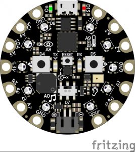
Microcontrollers are designed to meet specific input/output . As the purpose of the Circuit Playground Express microcontroller isn’t high performance, per se, but rather education, it is a bit more flexible than other microcontrollers. To meet various educational specifications, designers, engineers, and others came together to move from prototyping, likely at times using basic electronic components, wires, and breadboards, to ultimately create a diversity of integrated circuits put together on one printed circuit board to result in the Circuit Playground Express microcontroller. In shaping this tinker microcontroller, the intent was to provide us with flexibility to use the device in ways that can serve a range of open-ended learning and design specifications. As we’ll learn throughout this unit, it is a participatory design process that intentionally underdesigns the sociotechnical artifact to assure greater innovation-in-use by others.
Similar to a diagram showing the LED Sequin Integrated Circuit, this diagram of the Circuit Playground Express doesn’t provide specific descriptions of the electronic components actually built into the printed circuit board, nor how they are brought together with conductive materials. But all the same, they are miniature versions of the resistors, LEDs, and push buttons, as well as sensors, switches, speakers and other electronics, just in miniaturized form. They are soldered to a printed circuit board and connected together using sturdy conductive materials.
So before moving on, take a few minutes to learn about the Circuit Playground Express. The best way is to visit the the Adafruit Learning Center:
https://learn.adafruit.com/adafruit-circuit-playground-expressEspecially check out the “Overview,” “Guided Tour,” and “Pinout” sections to see the otherwise hidden details of the electronic components put together on this printed circuit board.
Guiding Questions
As you read, keep in mind these social guiding questions:
- Who shaped the designers and builders of the Circuit Playground Express to create it in this way?
- Was that shaping intentional, accidental, or a little of both?
- How does Adafruit’s goal of teaching electronics and learning to code fit into all of this?
- As a result of the design and implementation of the Circuit Playground Express, how are you being shaped?
- And how might that shaping ultimately result in the shaping of still other people?
Coding the Circuit Playground Express
We’re pretty familiar with our everyday general purpose computers that play an important role in running a wide range of applications continuously, or at selected times, to accomplish a diverse range of tasks. To access this book via a web browser, to communicate via email, to talk and text using a phone, to participate in social media, and so many other activities, you have become rather familiar with laptop and/or desktop computers, and smartphones, which are microcomputers. (Microcomputers are simply small computers that contain a microprocessor as its central processor.)
The instructions created to control or evaluate electronic components are commonly termed code. As coded instructions are brought together to control the complex operations of computers and other machines, they are typically termed programs. These days, doing this work is referred to either as . The specific words, characters, symbols and structuring of code to achieve the desired works are typically termed a .
As a general rule, microcontrollers are designed to continuously run a single application using a specific programming language.
The Circuit Playground Express has been designed especially for educational use and so works with a range of programming languages, including Microsoft’s education-friendly MakeCode block coding language, Adafruit’s CircuitPython extension to the Python programming language, and Arduino’s Arduino integrated development environment (IDE), written using the Java programming language.[1]
For the next few sessions, we’ll work with MakeCode using Adafruit’s website:
https://makecode.adafruit.comIt was designed to work specifically with their Circuit Playground Express. It has many similarities to Scratch, a programming language developed by the Lifelong Kindergarten Group at the MIT Media Lab.[2]
- Both use visualized blocks of code which can be combined to create error-free code which achieves a certain event.
- Both are freely accessible to anyone, and creators are encouraged to work collaboratively in online communities to share creations.
- Both are being used by a wide range of explorers, from those in the early grade levels to older adults, and all in between.
A key difference, though, is that Scratch focuses on creation of interactive stories, games, and animations visualized using sprites wearing costumes and performing on stage. Adafruit’s MakeCode is created online in a Circuit Playground Express prototyping space and tested in a visual simulator before code is then downloaded and moved to your physical Circuit Playground Express for live testing.
Exercise: Introducing MakeCode and Circuit Playground Express
Adafruit has worked extensively to come up with a range of introductory tutorials, courses, and web pages, along with a range of exciting projects for you to use the Circuit Playground Express in your everyday lives. Links to these can be found on the MakeCode homepage.
This next exercise is a remix of different projects and guides found through Adafruit and other sources. We’ll work to familiarize ourselves with coding concepts while also repeating certain LED and switch activities from the Orange Unit.
But first, let’s test the 10 general-use LEDs built into the Circuit Playground Express ring. Take four minutes to view this video showing the steps to write the MakeCode Animated Blinky FOREVER function, to save this to your laptop Downloads folder, and to flash this to the CPLAYBOOT device after connecting the Circuit Playground Express to the USB port on your laptop.
Steps
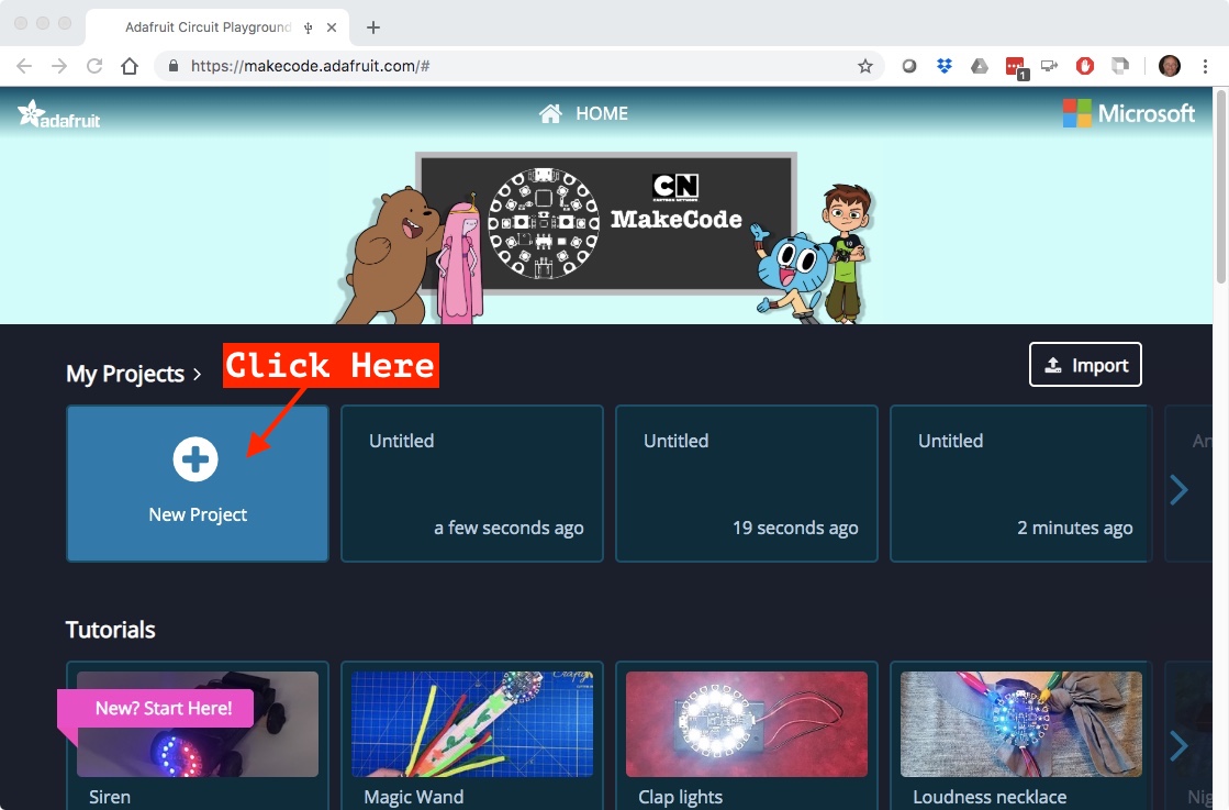
- In your laptop’s web browser, click on “New Project” from the MakeCode homepage.
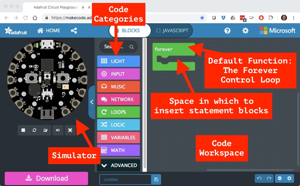
When programming in MakeCode, we select blocks from within one of the “Category” menus and drag those into the workspace. These are either dropped into an open workspace to create a new , like the default FOREVER loop, or within an existing function as a . All blocks in a category are color coded to match the color of that category as seen in the parent window. So we can tell that the green FOREVER block came from the green LOOPS category. MakeCode will automatically begin immediate testing of the code, if possible, in the simulator.
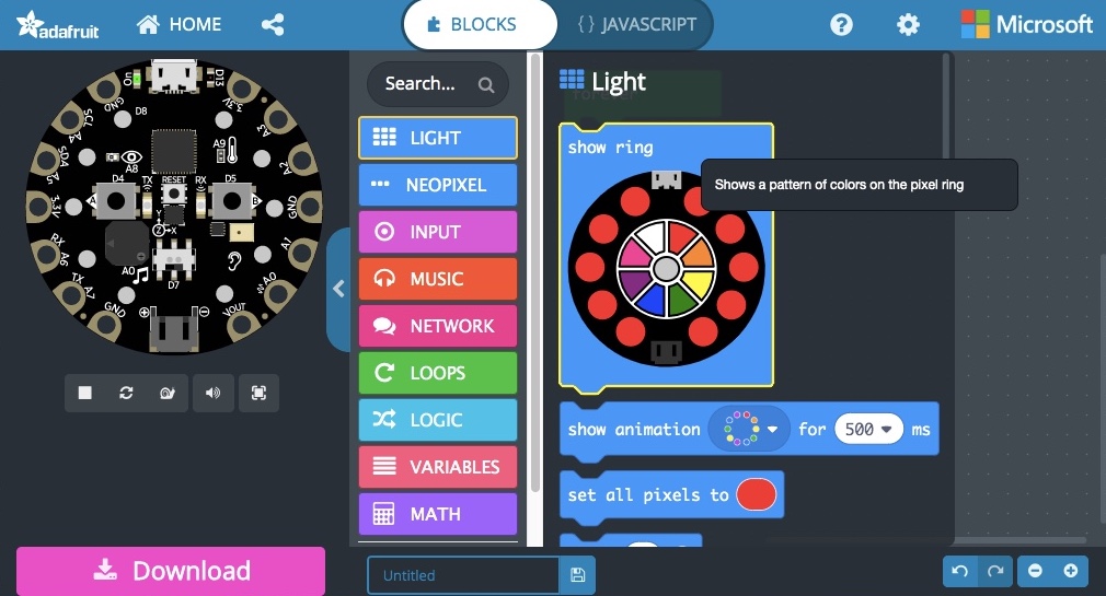
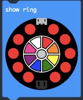
- In the LIGHT category, drag the “show ring” block and drop it into the .
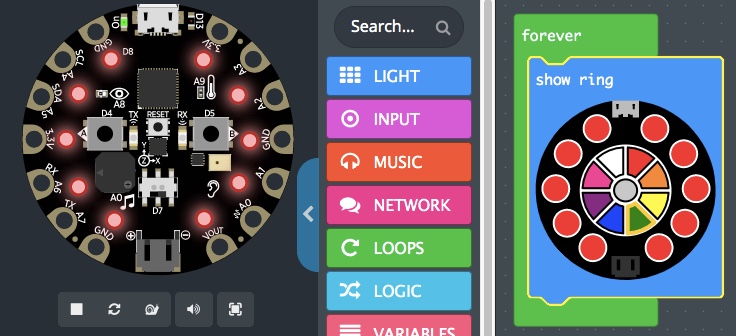
 By default, all 10 LEDs are set to red, and after a few seconds the LEDs in the simulator should also turn red.
- From the LOOPS category, drag the “pause” block and drop it below the “show ring” block, providing a statement to pause the loop for a set amount of time – by default 100 milliseconds.
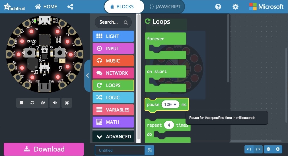
- From the LIGHT category, drag the “show animation” block and drop it below the “pause” block.
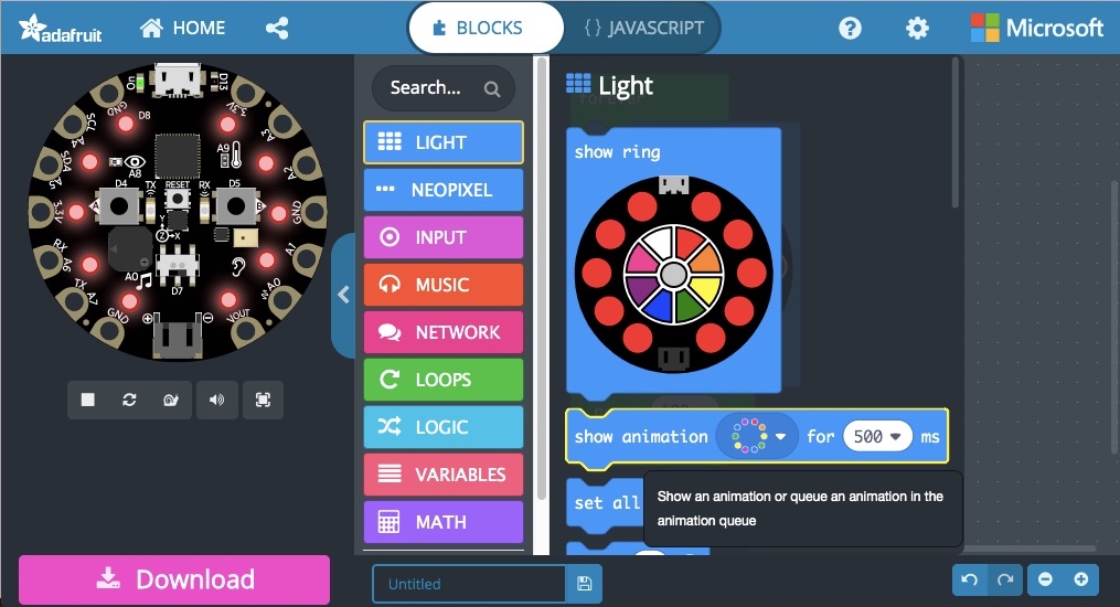
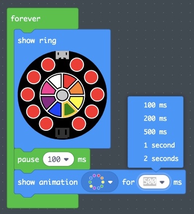
- Increase the “show animation” time to 2000 milliseconds, that is, to 2 seconds, by clicking on the default “500 ∇” setting and choosing 2 seconds.
- Right click on the existing “show animation” block and select “Duplicate” from the provided window that pops up.
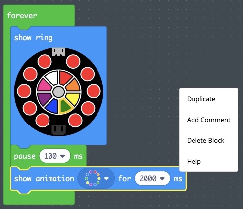
- Drag the second “show animation” block from within the workspace and drop it below the first “show animation” block.
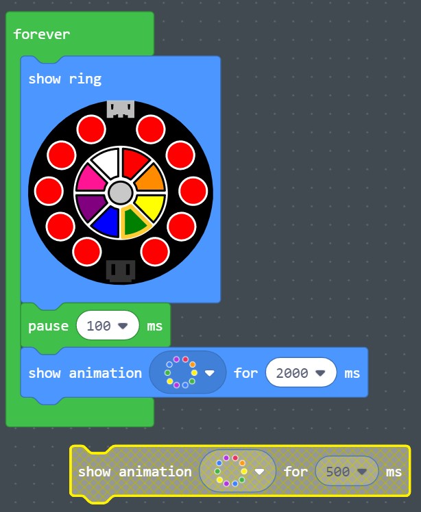
- Right click again on the first “show animation” block and select “Duplicate” from the provided window that pops up. This time it will duplicate its own block, and all blocks below it. In this case, that’s only the second “show animation” block. Place these below the first two.
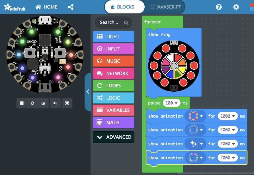
- As of now, the simulator should “show ring,” pause for 100 milliseconds, then “show animation” default for 4 x 2000 ms, or 8 seconds. Click on one each of the “show animation” block animation ∇ visuals and select from the six options provided.
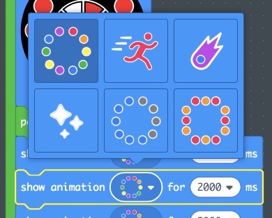
- This is rapid , so only take a few moments to create an acceptable testing prototype through modifications of the six lines of code now within the FOREVER loop, and through viewing of the results within the simulator display.
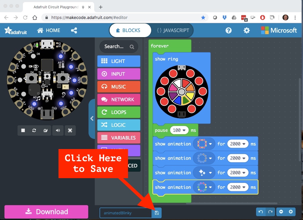
- At the bottom of the MakeCode window, replace the word “Untitled” with “animatedBlinky” and click the save icon to the right of the filename.
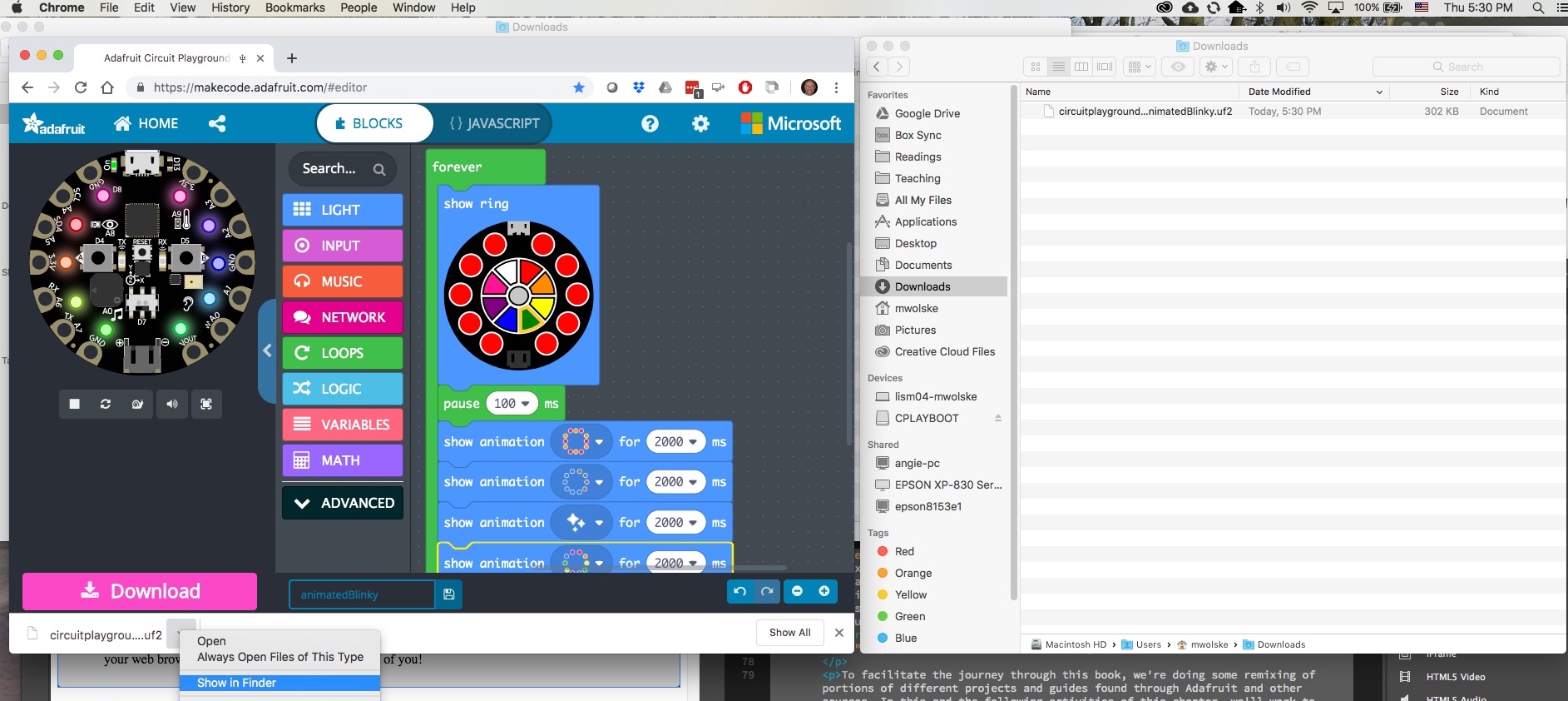
- You now need to flash the code to your Circuit Playground Express. You can review this section of the previous video to see the specifics on these steps again:
- Connect your personal laptop to the Circuit Playground Express via a USB to micro USB cable.
- The lights on the Circuit Playground Express should start flashing different colors if this is the first time you’ve plugged it in.
- Press the center “reset” push button on the Circuit Playground Express.
- You may need to push it longer or shorter to move from flashing LEDs to a solid green set of LEDs.
- This indicates it’s ready to be physically reset with new code.
- In your Windows Explorer or Mac Finder window, you should now see the device named “CPLAYBOOT” listed. Here’s a short section of the earlier video demonstrating these last steps:
- Drag the file
circuitplayground-blinky.uf2from your downloads folder and into the CPLAYBOOT device. This saves the MakeCode you created onto the Circuit Playground Express in away that allows it to be understood and followed by the Circuit Playground Express.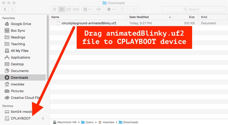
- Connect your personal laptop to the Circuit Playground Express via a USB to micro USB cable.
Key Takeaways
- A block code programming language and Integrated Development Environment (IDE) like MakeCode allows you to drag and drop error-free sections of code from the CATEGORY list into a working programming screen.
- Microcontrollers such as the Circuit Playground Express are typically directed by one or more small programming or functions with instructions which are continuously run unless the microcontroller is disconnected from power or otherwise turned off.
- To achieve this, the MakeCode environment launches a FOREVER block by default when you open a new project. This creates a continuous , a used in computer programming to loop back around.
- We dragged and dropped six blocks that served as individual lines of code to be executed in each time the FOREVER loop was restarted at the top.
- A live-screen simulator automatically restarts and runs the updated code each time you drag and drop a block, letting you test your program in a browser.
- The Circuit Playground Express is designed by default to allow you to then flash the code you created onto it, at which time the physical microcontroller will restart and run the code, just like the simulator.
Choose Your Own Adventure
A Person-Centered Guide to Demystifying Technology is an introductory textbook using a variety of hands-on exercises to evolve a more holistic and nuanced understanding of the sociotechnical artifacts we use as a daily part of our professional lives. It seeks to develop a critical approach to sociotechnical artifacts and to advance community agency in appropriating technology to achieve our individual and community development goals. As we’ve probed deeper, we’ve begun to expand our understanding of innovation beyond the package inside a box, but to also include the set of practices and remixes that emerge from the social setting of its use. We’ve also explored the hidden and forgotten innovators of technologies, including technologies beyond those defined as innovative within male-dominated professions and monopolies.
Working through this space is messy even at the best of times as we work to unpack the social and technical bits and their underlying, non-neutral shapers. And so the exercises seek to find a means through which a broader Community of Practice collaboration is possible. For the Blue Unit, this has been done through the selection of the education-focused Circuit Playground Express microcontroller board, and related exercises that explore core programming concepts through the use of the block-programming language MakeCode.
Alternative Programming Adventures
Whether or not you enter into this book with a background in programming, you may want to choose an alternative programming adventure to MakeCode to perform these exercises. Or you may want to do the exercises following the written MakeCode instructions, and then do your own innovation-in-use remixes using an alternative programming language. To that end, the Circuit Playground Express is compatible with three major text-based programming languages, including:
- JavaScript: a high-level programming language originally focused on livening up web pages through the use of its plain-text scripts. While its naming includes the term Java, a general-purpose programming language, it is independent from it and includes important features that make it a “safe” programming language that can be used with web pages and on web browsers in ways that Java cannot. Of special note, the design choices incorporated into JavaScript make it an ideal complement to the block-based MakeCode programming language.
- It’s easy to switch between MakeCode and JavaScript with a click of the code selection window options at the top, switching between adventure types. In this way JavaScript might prove an ideal text-based complement to the block-based MakeCode throughout the exercises of the Blue Unit to Do Something New!
- Python: a popular Open Source Software programming language that has proven very helpful within educational contexts as well as within the broader programming community. Its support of and packages means it can easily be reused in new projects. And as is the case here, it can be expanded to serve special use contexts, such as with microcontroller boards like the Circuit Playground Express. CircuitPython is based on Python and provides the essential hardware support needed to work with microcontrollers while including the Python coding base.
- The Circuit Playground Express is CircuitPython-ready, but does not have CircuitPython installed by default. This is because you can only work with one programming language at a time and MakeCode was chosen as the perfect introductory pathway. However, it’s easy to install CircuitPython. When installed, a new CIRCUITPY drive will appear in addition to CPLAYBOOT. NOTE: be sure to copy your .py program files to CIRCUITPY as that’s the only place from which they will run. The Adafruit Explore & Learn site has more to get you started with CircuitPython on the Circuit Playground Express.
- To go back to MakeCode, all you need to do is flash your selected MakeCode .uf2 file to CPLAYBOOT. NOTE: in so doing, you are also uninstalling CircuitPython; that said, you can switch between these regularly and often. Adafruit provides a helpful guide on Moving Circuit Playground Express to MakeCode.
- Arduino: a programming language adding a library of hardare interfaces to the C/C++ programming language. The Circuit Playground Express is Arduino-ready and you can find out more on this from Adafruit. While Arduino outperforms MakeCode/JavaScript and CircuitPython when run on microcontroller boards, it can take more time within development uploading/compiling and memory management. As such, the other two are recommended for the exercises of the Blue Unit.
The adventure is yours for the choosing. While it’s important to exercise your choice in ways that help you reach a sufficient state of “Yet” with regard to the key learning outcome objectives within the unit, it’s likely you have as many and more of your own valued beings and doings that you are working towards. It is our intent to assure you have choices and the means to exercise and achieve these choices in support of those values.
Exercise: Using Momentary Switch Circuits With Conditional Code
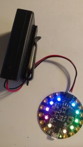 The animated blinky exercise gave us a chance to test out the MakeCode web browser. It also introduced us to the downloading and flashing of code to our physical Circuit Playground Express.
From here, you could further tweak the light display, unplug the Circuit Playground Express, connect it to a portable battery source, and voilà! Now you can carry this around after dark as you walk or bike home!!
Now let’s try using inputs, like the left and right momentary switches of the Circuit Playground Express, to determine the state of the LEDs. So far the sequence of our FOREVER control flow statement loop is run precisely the same over and over with no intentional changes. Using switches to turn on an off LEDs in our breadboard circuits is an example of .
Let’s work to do the same thing using the Circuit Playground Express LEDs and switches.
For this activity, we’ll repeat our Pi-Controlled LEDs activity from the Orange Unit. In that exercise, one white LED was constantly on. Two more white LEDs only came on when the left switch was pressed down. The blue LED, on the other hand, was on unless the right switch was pressed down. Let’s use MakeCode to do something similar on the Circuit Playground Express. This is an example of taking the insights gained from the many prototypes done with a breadboard and electromechanical components, and using them to extend our prototyping at a higher level of using a microcontroller.
One of the most common conditional statements is the , also referred to as an “If…Then…Else” statement. In our case, we’ll use this statement such that if the button A is pressed then turn a white LED on, else turn/leave it off. On the other hand, if button B is pressed, then turn a blue LED off, else turn/leave it on.
An important first step in coding is to items before moving on to the regular work of the code. In MakeCode, this is done with the “ON START” initialization control flow statement block. Any lines of code in this block are done in the order listed, and are done only once when power is first provided to the Circuit Playground Express. Hence the term initialization. We’ll use this to set a brightness for the LEDs and turn on and leave on another white LED as we’ve done in the Orange Unit exercises.
Let’s get started.
Steps
- On the MakeCode homepage, click to start a new project.
- From the LOGIC category, drag an “If…Then…Else” block and drop it into the FOREVER loop.
- From the INPUT category, drag a “button A is pressed” block and drop it within the <true ∇> window, like so:
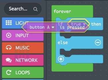
Notice in the image that the <true ∇> and <button A ∇ is pressed> windows both have a yellow border around them. This indicates that, if you release the mouse or touchpad button now, the upper Button A window will be dropped in the the lower True window. It’ll take a little practice to get good at this, and I still find I sometimes drop one window into the wrong lower window. Fortunately, by dragging and dropping, it can be moved to the intended window from wherever it was accidentally placed. - Time for a design choice. Which button will work with the normally off white LED, and which the normally on blue LED? For now, let’s go with button A = white LED off unless pressed.
- From the LIGHT category, within the More section, drag the “set pixel color at” block and drop it into the then section.
- Change the at subwindow to 4, and change the color from red to white.
- In the simulator, press the “A” button on the left. Notice the LED below the musical note symbol turns white and stays so.
-
- Could it be that the location of the buttons in the simulator looks similar to the location of the buttons on the breadboard sitting next to my computer workstation? Design influences come from many physical as well as social and mental influences!
- The “else” part of an is just the place we need next so that we can turn/leave the white LED off if the “button A is pressed” condition above is NOT true.
-
- Take another “set pixel color at” block and drop it into the else section, changing the at to 4, and the color to black.NOTE: You can do this either by duplicating the “set pixel color at” block from the then section and then dragging the duplicate into the else section, or you can enter into the INPUT category and drag a new “set pixel color at” block from there to drop into the else section.Our white LED is now off on the simulator unless we press button A!
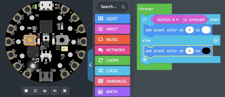
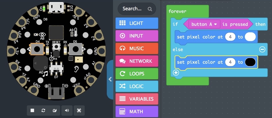
- Take another “set pixel color at” block and drop it into the else section, changing the at to 4, and the color to black.NOTE: You can do this either by duplicating the “set pixel color at” block from the then section and then dragging the duplicate into the else section, or you can enter into the INPUT category and drag a new “set pixel color at” block from there to drop into the else section.Our white LED is now off on the simulator unless we press button A!
- Right click in the area of the “then” statement text, and choose duplicate from the pop-up window.
- Drag the duplicate “If…Then…Else” logic block and drop it below the + symbol at the bottom of the current “If…Then…Else” statement block.
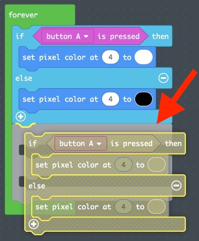
Second “If…Then…Else” logic block properly placed below first “If…Then…Else” logic block. 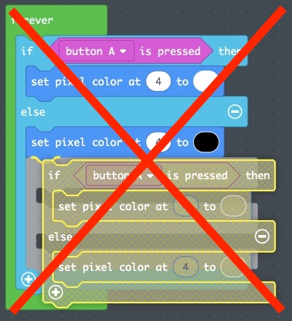
Second “If…Then…Else” logic block incorrectly placed within “Else” of first “If…Then…Else” logic block. It is important to drop this into the right location. In the images above, dropping it below the current “If…Then…Else” statement block specifies that, during each pass through the sequence of statements within the FOREVER loop, we will first do the top “If…Then…Else” conditional logic block, then the second “If…Then…Else” conditional logic block.The image on the right, crossed out in red, demonstrates how we could have otherwise done a single “If…Then…Else” conditional logic block, and one if it is NOT true. We would turn/leave the white LED #4 off and then check the conditional as stated in the “If…Then…Else” within the else statement. More on this later.
- In the second “If…Then…Else” conditional logic block, change button A to button B and the at statement from 4 to 5.
- To reverse the conditions determining when the LED turned on, in the second “If…Then…Else” conditional logic block, change the white color of the pixel within the “then” section to black. Change the black color of the pixel within the “else” section to blue.
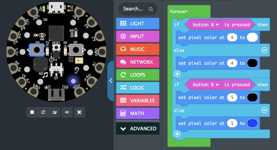
- Experience has shown these LEDs – especially the white LEDs – can be very bright, sometimes alarmingly so for those with certain visual functional diversities. Before flashing this over to the physical Circuit Playground Express, let’s add in an “ON START” initialization block to determine the brightness of the LEDs, and to also turn on one of the white LEDs as a working symbol, as we’ve used in the Orange Unit prototypes.
- From the LOOPS category, drag an “on start” initialization block and drop it into an open area of the workspace.
- From the LIGHT category, drag a “set brightness” block and drop it into the ON START initialization block.
- From the LIGHT category, drag a “set pixel color at” block and drop it into the On START initialization block underneath the “set brightness” block.
- To finish, change the brightness from 20 to 5, and the set pixel color at 0 from red to white.
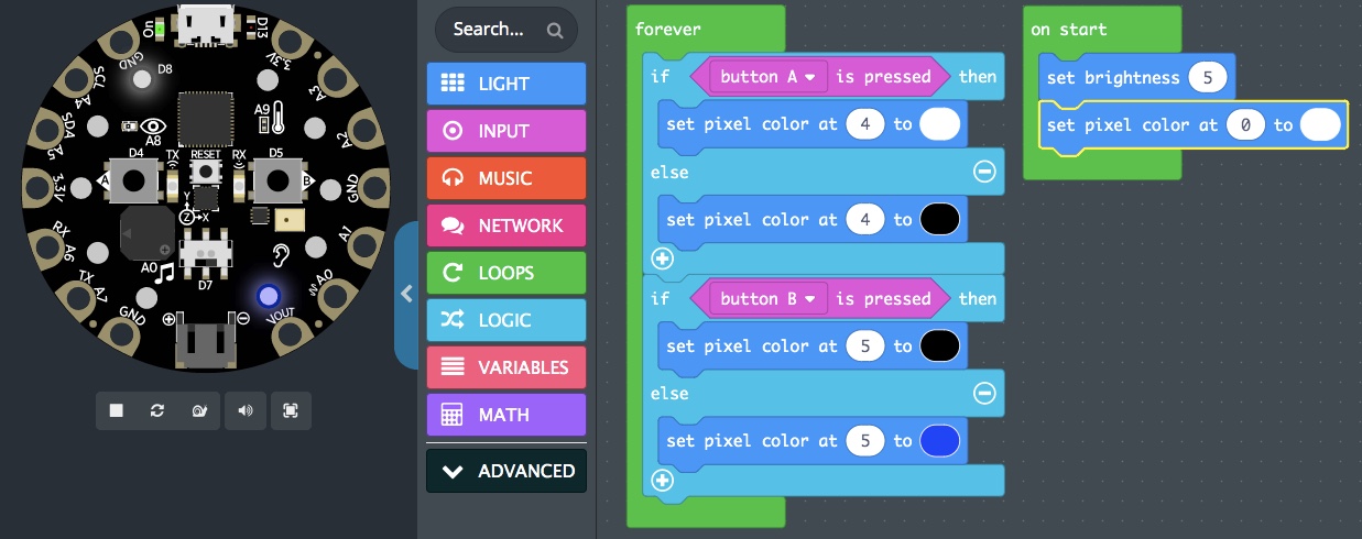
- Do further testing in the simulator until you think it is working as it should.
- In MakeCode, change the file name from “Untitled” to “pushButton,” click on the save icon, and Download.
- On the physical Circuit Playground Express, push down the “reset” button, and drag the new
circuitplayground-pushButton.uf2file to the CPLAYBOOT device. - Do initial testing on the physical device, confirming it is working as it should, or identifying fixes needed within the code. This can include adjustments in the overall design, not just in the code as created through the above steps.
- Make any changes as identified on the physical device within MakeCode, test further in the simulator, save a new copy and flash it to the physical Circuit Playground Express, and do additional testing there. Repeat this process until it works well for you, for your co-explorers, and perhaps even for your intended audience!
Key Takeaways
In this exercise, we extended our electronics prototyping skillset using the Circuit Playground Express microcontroller.
- We coded within the FOREVER function loop, extending the number of statements, or lines of code, that occur within each sequence through this loop.
- We studied the “If…Then…Else” conditional control flow statement, which uses a logic question such as “If button A is pressed,” and provides a platform to then indicate that action when true. In our case, that meant turning on a white LED. The “Else” section lets us specify what to do if the question is false. In our case, that meant turning off, or leaving off, that same white LED.
- We found how it is often important to initialize items, for instance, by setting the brightness to a certain chosen level before those LEDs are turned on.
- We worked in multiple layers of abstraction, while balancing our prior and current knowledge and skills and our considerations regarding investment of time and capital to move through this activity.
- There’s quite a bit of electronics now “under the hood,” and much of the engineering specifics are no longer known by us, although as used it performs much the same as did our later breadboard prototyping in the Orange Unit.
- How our blocks turn into text before being compiled and turned into machine-readable code is now hidden from us, but this trade-off gives us a relatively easy way to dip our toes into coding.
- The programming code that takes our FOREVER function loop and ON START initialization control flow statement and uses them to change to state of the electronics as instructed is also largely underneath the hood and unknown to us. In its design, though, is a pathway for us to do some extensive innovation-in-use of the software and associated electronics to meet our own chosen valued design choices.
- Abstractions, when designed and implemented well, provide us with new opportunities to go places we had otherwise only dreamed. But, there’s always a risk that underneath those hoods are choices that ultimately may take us places we consider problematic or don’t value. No matter the stage of design and implementation we find ourselves at, it is valuable to pause regularly throughout and reflect on the seen, the unseen, and the unforeseen in these sociotechnical artifacts.
Exercise: Testing Out Innovation-in-Use to Build a Five Digit Counter
Our Circuit Playground Express now performs as a tool fairly similar to the one we prototyped on our breadboard previously. But with the Circuit Playground Express, we have more LEDs available. This might be a good way to further expand our budding design, prototyping, and coding skills.
With five LEDs in the area of button A, what if we used them as a five digit counter?
Through trial and error, I found that the programming code behind MakeCode preset the 10 LEDs with numbers 0 to 9, in which LED 0 is nearest the green “On” LED of the Circuit Playground Express, and LED 9 is just below D13 and just above the A9 thermometer symbol of the Circuit Playground Express.
This brings to mind that there are five digits on the same half of the Circuit Playground Express as button A, numbered 0 to 4. There are five additional digits on the other half of the Circuit Playground Express, those numbered 5 to 9, on the same side as button B.
This design matches well the normative design of the human body with two hands (analogous to two buttons) with five fingers on each (analogous to five LEDs in proximity to each of the two buttons). This prompted new ideas for using the Circuit Playground Express to further advance our coding logic flows.
For this exercise, let’s equate one push of each button with raising the fingers within that analogical hand. Once all five LED digits are raised within a hand, one with each new press of the associated button, the next press of the button will turn off all five of its LEDs.
Knowledge Probe
First, let’s think through the logic of this new design a bit more, starting with the five LEDs of button A, LED pixels 0 to 4.
- In the last activity, for each pass through the FOREVER sequence:
- If button A is pressed down, pixel at 4 is set to color white, whether it was already set that way or not.
- If button A is not pressed down, pixel at 4 is set to color black, whether it was already set that way or not.
- This is an example of . In combinational logic, the result depends only on the current states of the inputs. What we do in each sequence is determined just based on the current state of the system. It is not based on any past states of the system.Sometimes combinational logic is the absolute best choice, like what I do if I see a squirrel trying to eat fruit from my garden. It doesn’t matter whether this is the first time or the 50th time. Combining species (squirrel), location (garden), conditions (fruits ripe or nearly so), and knowledge (squirrels eat this type of fruit), I’ll chase it away. This is combinational logic.Sometimes combinational logic is the choice we go with just because it’s at hand. I’ll just keep chasing off the squirrel from the fruit tree because it’s right next to my easy chair where I’m reading a book. But other times, we may use past logic to influence future logic. Perhaps squirrels haven’t been here before, so chasing it off five times might make good sense. But on the sixth attempt to invade our fruit tree, we might logically consider it’s time to do something more drastic than just chasing it off.Then there are times when combinational logic just doesn’t make sense. Consider the ceiling lights in a kitchen. What if combinational logic was only available to turn them on? Combining intent (cooking dinner), conditions (after dark), and knowledge (I’ve previously used my vision to select and use ingredients) suggests we turn on the light. If this meant we needed to walk over and push and hold down a button to keep the light on, this combinational logic would keep us from doing the rest of the activities.
- In this activity, we not only want the press of the button to turn on an LED; we want it to move down the line, lighting a sequence of up to five LEDs. What action using Button A could change the pixel number being lit next?
- Each new pass through the FOREVER sequence while button A is pressed, move to the next pixel?
- Every 100 passes through the FOREVER sequence while button A is pressed, move to the next pixel?
- At initial change of button A from not pressed to pressed, move to the next pixel?
- Something yet different from that?
- Back when I used to use a click counter to keep track of an event, a clicker either: 1) started a counter that ran until I did a second click, which matches well a and b above, or 2) it increased the count by one every time I hit that clicker, which matches well with option c above. For now, let’s go with option c, then.
Steps
- Start a new project in MakeCode.
- From the LOOPS category, drag over an “on start” initialization block, and drop it somewhere in the workspace.
- From the LIGHT category, drag over a “set brightness” to the ON START initialization block and set it to 5 (or your chosen value) to keep the LEDs from being too bright.
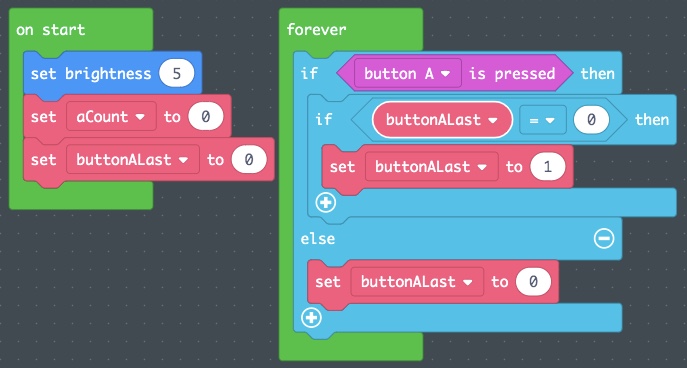
- For this exercise, we’ll need some to keep check on specific things. We’ll start by creating these variables within the VARIABLES category. Create each by clicking on “Make a Variable”:
- Name one “aCount”. We’ll use this to determine how many times the button has been pressed recently.
- Name one “buttonALast”. We’ll use this to remember if it was pressed down during the last sequence with the number 1, or if it was not pressed down during the last sequence with the number 0.
- Using variables to remember recent past states and to determine current events is the basis for . What to do at this point in a sequence is determined not just on current state, but also on past states.
- From the VARIABLES category, drag a “set _____ to 0” to the ON START initialization block. This will be labeled the same as the last variable created.
- Copy two of these over to the ON START initialization block.
- Use the ∇ label to drop down options, and set one to aCount and the other to buttonALast.
- Leave each set to 0 within the ON START initialization block.
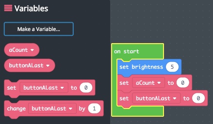
- As in the last exercise, from the LOGIC category, drag over an “If…Then…Else” block and drop it into the FOREVER function.
- As before, from the INPUT category, drag over a “button A is pressed” block and drop it into the <True ∇> window.
- This time, rather than turning a specific pixel white or blue, we’ll instead use a new “If…Then” block (no “…Else” needed here) within the “Then” section. We’ll use this to determine whether this is a new press of the button, or an ongoing press of that button.
- From the LOGIC category, from within the Comparison section, drag over a <0 = 0> block and use it to replace the <True ∇> of this second “If…Then” logic statement.
- From the VARIABLES category, drag a “buttonALast” variable block and replace the left “0” of the comparison we just added. Leave the other “0” as is.
- This “If…Then” conditional is now checking to see if button A was NOT pressed previously as a first step within the “If…Then” conditional in which “button A is pressed” was True.
- To complete the sequential conditional logic being setup with the buttonALast variable, we need to:
- Drag the “set _____ to 0” variable block within the VARIABLES category and drop it into the else section of the parent “If button A is pressed” logic statement. Update it to read “set buttonALast to 0,” as this “else” section is reached only when button A is NOT pressed. We want to remember that in the past iteration of this FOREVER function sequence, button A was NOT pressed.
- Drag a second “set _____ to 0” variable block within the VARIABLES category and drop it into the “Then” section of the “If buttonALast = 0” logic statement. Update it to read “set buttonALast to 1” as this “Then” section is reached when button A is first pressed, and we want to remember it is already pressed moving forward into future iterations of this FOREVER function.
Looking at our code, we see that within the FOREVER loop, we now have a parent “If…Then…Else” block that uses a “button A is pressed” block conditional as its starting point.
- If “False,” that is, button A is NOT pressed, we move to the “Else” section and set the buttonALast Variable to 0, or False.
- If “True,” that is, button A IS pressed, we move to the “Then” section. But rather than immediately taking an action, this time we first do another logic check, this time, whether button A was NOT pressed last time using an “If buttonALast = 0” condition. That’s because we already know we set the variable buttonALast to 0 whenever the “button A is pressed” condition is “False.”
- Now, only when “button A is pressed” is “True” AND “buttonALast = 0” do we change the block Variable to “set buttonALast to 1.”
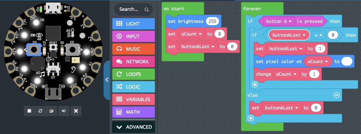
- Within the “If buttonALast = 0 Then” statement, add a “set pixel color at” block from the LIGHT category.
- From the VARIABLES category, drag over an “aCount” block and drop it into the 0 window of the new “set pixel color at” block, so that it now reads “set pixel color at aCount.”
- Change the red window to white.
- From the VARIABLES category, drag a “change _____ by 1” block and drop it under the “set pixel color at” block. Use the ∇ key to set this block up to read “change aCount by 1.”
- To add a conditional limiting the number of pixels turned to white using button A, we need yet a third embedded “If…Then” logic statement, this one as with the the top parent including an “…Else.”
-
- From the LOGIC category, drag over an “If…Then…Else” block and drop it under the “set buttonALast to 1” block within the “if buttonALast = 0 Then” statement.
- Drag the blocks “set pixel color at aCount to white” and “change aCount by 1” into the “Else” section of this new “If…Then…Else” statement. It should look as follows:
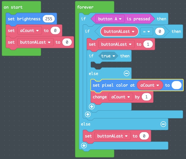
- From the “Comparison” section of the LOGIC category, drag over a “<0 = 0>” block and replace the “true” window of the new “If…Then” statement.
- From the VARIABLES category, drag an “aCount” block and drop it in the left 0 window.
- Change the “= ∇” window to “>”.
- Change the right 0 to 4.
- Now, “If aCount is greater than 4, Then” we can turn all of the white pixels on the button A side to black. Else, we’ll turn the next aCount to white.
- To turn the five button A pixels from white to black, we’re going to use a new control flow statement called the
-
- From the LOOPS category, drag a “for index from 0 to 4” block and drop it within the “If aCount > 4 Then” statement.
- From the VARIABLES category, drag an “aCount” block and drop it where the “index” block is now located within the new FOR loop.
- From the LIGHT category, drag a “set pixel color at” block and drop it inside the FOR loop.
- From the VARIABLES block, drag a “aCount” and drop it into the new “set pixel color at” block, replacing the 0.
- Change the red window to black in this “set pixel color at” block.
- This FOR loop resets the aCount back to 0, goes through the “Do” section, then increases the aCount by 1 and repeats the “Do” section, continuing until it reaches the maximum number. In our case, this means it will go through aCount from 0 to 4, turning the pixels black.
- Finally, add in a “set _____ to 0” from the VARIABLES category and drop it underneath the new FOR loop, using the ∇ to set this to a “set aCount to 0” block.

- Use the simulator to test this prototype. Every sixth press of button A should now reset our counter to zero pixels lit. If this is Not Yet the case, Fail Forward using the troubleshooting process to reach Yet.
- Once all looks good in the simulator, save this code as pushButtonCounter, flash it to the physical Circuit Playground Express, and give it a field test.
Ta-da!!! Now, let’s create a Button B counter in blue to stay with the theme of that button.
Steps
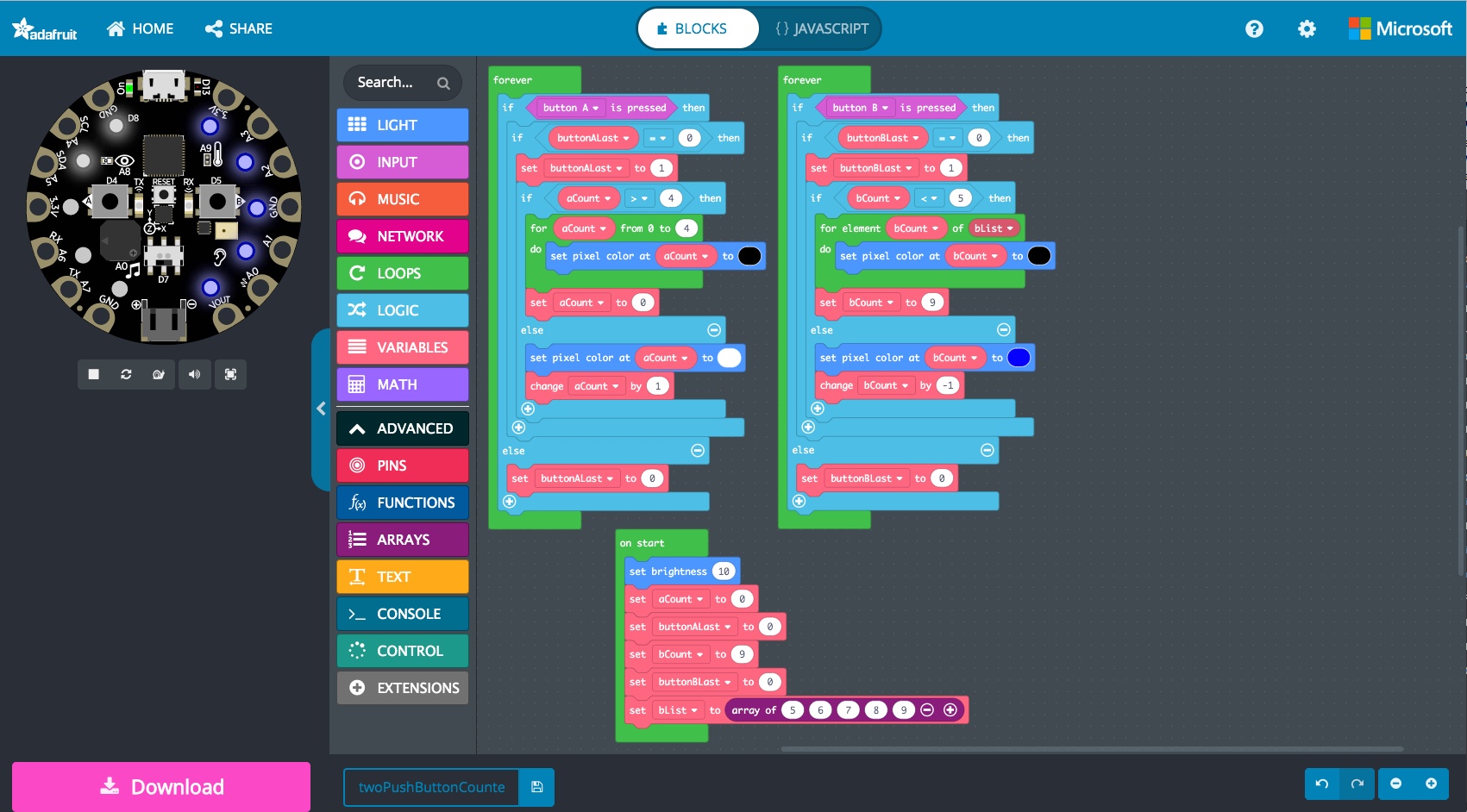
Rather than taking the time to go through the copying/pasting and remixing of the first “button A” FOREVER function to create a second “button B” FOREVER function step by step, let’s commit the time to noticing the key changes needed to have this fit within the design profile listed above.
- In your laptop web browser, download this UF2 code:
circuitplayground-twoPushButtonCounters.uf2- If it does not do so automatically, select to download this file.
- Flash the downloaded
circuitplayground-twoPushButtonCounters.uf2file to the physical Circuit Playground Express and perform some initial testing of this prototype.- Does it fit the design profile as stated above?
- Does it work well for you and your valued doings?
- Go to the MakeCode homepage and drag the downloaded file
circuitplayground-twoPushButtonCounters.uf2onto the MakeCode screen. Take a minute to test this prototype in the simulator. How does it compare to the physical testing process? - Both FOREVER functions have 19 “lines of text,” so to speak, within the blocks.
- How many are the same? Why?
- How many are different? How might they have changed?
Side Note on the For Loops
Within the Button A FOREVER function, the FOR loop is written as:
for aCount from 0 to 4, set pixel color at aCount to black
In this “For” control flow statement, aCount starts at 0 and the pixel at 0 is set to black. aCount is increased by one, and if it’s still less than or equal to 4, that pixel is set to black. In this way, it sets pixels 0, 1, 2, 3, and 4 to black.
Within the Button B FOREVER function, the FOR loop is written as:
for element bCount of bList, set pixel color at bCount to black
Since Button B does not work with pixels 0, 1, 2, 3, and 4, but instead works with pixels 5, 6, 7, 8, and 9, this basic “For” control flow statement wouldn’t work. So in the ON START initialization control flow statement, a new bList array was created, with the numbers 5, 6, 7, 8, and 9 put into that . In this “For” control flow statement, every bCount of bList is used to do a “set pixel at” action.
An aList could have been created with 0, 1, 2, 3, and 4 within this array, replacing the “for aCount from 0 to 4, do” statement with “for element aCount of aList, do” statement. In setting up the button A FOREVER function, you stepped through the simpler version as MakeCode wrote the block code with this simpler FOR loop block. But both forms of the FOR loop function the same, and using the list arrays would give greater flexibility moving forward. This demonstrates how there are often multiple ways to execute code, some of which depend as much on programming preference as on performance.
Key Takeaways
Sequential logic is used when past conditions (such as the previous state of a switch or the last LED that was lit) should impact what is to be done in the current sequence of a control flow statement. In our case, this was used to determine actions to be done or not be done within a sequence of “If…Then” control flow statements.
Multiple embedded “If…Then” and/or “If…Then…Else” control flow statements can be used to move from more general True/False, Yes/No logic questions to more specific logic questions.
Variables are data items whose values can be changed. In this case, the variables aCount and bCount were used to determine which of five pixels associated with button A and button B, respectively, should be lit. The variables buttonALast and buttonBLast were used to only change the condition of an LED pixel when the button’s state is first changed.
Arrays provided a list specific to button B that was used to give greater flexibility regarding which LED pixels should be turned on or off. This is an example of how, often in computing, an indexed set of related elements can prove extraordinarily useful to expand the possibilities regarding data sets held within variables.
Choices shape our pathways forward. Sometimes the way forward is to use written guides and hints, or even to download and use already written code. While useful, it can make it more difficult to know what has shaped these resources as compared to those times when you participate in a community of practice to design and prototype something. Even then, it is almost always the case that you are working at a relatively high level of abstraction, in which case there are still hidden choices underneath the hood.
As an example of this last takeaway, you may find it helpful to glance at the JavaScript text to which the blocks are converted in the MakeCode twoPushButtonCounters code. The “for aCount from 0 to 4, do” as used in the button A forever function could have been changed to “for bCount from 5 to 9, do” in the button B forever function. But a MakeCode block for this type of for loop was not created, and so could only be done by making this change to the code in JavaScript, potentially a more difficult process for those shifting from block to JavaScript programming languages.
Wrap Up
To build further on the key takeaways from the above three exercises, take 11 minutes to watch this video on “Programming Basics: Statements & Functions” from Carrie Anne Philbin’s Crash Course Computer Science series hosted by PBS Digital Studios:
Coders shape how things work even as they are shaped by how past coders shaped the code. We started with the blinky code. But behind that code was more complex code, hidden from view.
- Who set up the blocks we used to work the way they did?
- How did it work well for us? How could it have worked better?
- Did we always understand how one block worked compared to another? Why or why not?
By the end, you followed instructions to create your own functions with loops and variables. Each function included other, hidden functions and variables incorporated into sequences of code operating sometimes under only certain conditions.
There’s a trend to more strongly shape programs and the distributed apps based on those programs. In doing so, control is taken away from us. In this chapter, we’ve worked to discover how we can get control, but only if the Integrated Development Environments like MakeCode and programmable electronic systems like the Circuit Playground Express have been designed and implemented in ways that facilitate innovation-in-use by those at every level of the social technical artifact.
- In what ways have you been shaped by the Circuit Playground Express, selected electronics, MakeCode, and these exercises?
- In what ways have you helped to shape the Circuit Playground Express, selected electronics, MakeCode, and these exercises?
- If you were return to the top, in what ways might you work to shape the Circuit Playground Express, selected electronics, MakeCode, and these exercises?
- Who might be impacted by these things because of the various mutual shaping and amplification by the many people involved: individuals and communities of practice with unique histories, intersectionality, expertise, valued doings, and power, privileges, and oppressions?
Comprehension Check
We’ve spent time learning how to write basic programming code to create control flow statements such as FOREVER and FOR loops, ON START initialization, and “If…Then” conditional statements. We’ve used variables and arrays to facilitate use of data within the code to facilitate coding through abstraction. And we’ve used FOREVER and ON START functions to break down code into distinct units.
Let’s check our learning of these core coding concepts by bringing the following blocks together to create a new ON SHAKE function that plays a short siren and blinks between two different LED pixels rings before turning all LED pixels off. This should be added to the Button A and Button B Five Digit Counters.
The design criteria includes:
- A siren should cycle between playing a low note and a high note three times.
- The ring of LED pixels should change between two different LED colors four times.
- At the end, all sound and all LED pixels should be turned off.
- This sequence of events should only happen when the slide switch is moved to the right. If the slide switch is moved to the left, no siren or LED pixel rings will occur.
- Regardless of the state of the slide switch, the five digit counters should continue to work whenever the Circuit Playground Express is not being shaken.
Each of the following should be used within the ON SHAKE function:


![]()
When working with electrical components, a circuit is a complete, closed path that allows an electric current to flow. In this book, we work with active circuits that begin at a source voltage, pass through one or more electrical components, then end at the return, or ground.
When a number of insulated wires are brought together to create a flat ribbon of wires, this is called a ribbon cable. Ribbon cables may have a plastic box with solid metal pins extending out from the other side, in which case it is known as a male header. Other times, a plastic box is made with holes into which metal pins can be inserted, in which case it is known as a female header.
Integrated circuits (ICs) are semiconductor wafers which contain a collection of tiny resistors, capacitors, and transistors. These can then be built to serve a wide range of electronic functions. In practice, larger sized electronic components used to build circuits are first tested using materials like breadboards for rapid prototyping. They are then redesigned to be built into integrated circuits and optimized for regular, more standardized use. At times, a mix of electronic components along with integrated circuits are themselves used on breadboards to do further rapid prototyping of yet larger circuitry. The 5-Key Capacitive Touch Sensor included in the kit for this book contains a mix of integrated circuits. Examples of integrated circuits include: processors, memory, controllers.
A printed circuit board is a board base made of fiberglass or glass-reinforced plastic with one or more layers of copper or other conductive traces placed on one or both sides of the board base. If you've ever tie dyed a shirt, you've got a good starting point for considering the printing process of a circuit board. Individual electronic components and integrated circuits are then soldered onto specific trace paths to build complex electronics. A small printed circuit board was used to build the 5-Key Capacitive Touch Sensor used in our kit.
Often called "specs," specifications are formalized practices created using accredited technical standards developed and adopted using an open consensus process under guidelines of a standards body, or using de facto technical standards developed and owned by a single group or company.
Coding is the practical work of using a system of words, letters, figures, and other symbols to substitute for another set of words, letters, figures, and other symbols. Coding can include the creation of codes of practice and codes of ethics within a profession, codes of classification or identification, and codes of information and instruction within a technology. Decoding is the work of moving a code back to the original system of words, letters, figures, and other symbols. This is compared to programming, which is the creation of a planned series of events, items, or performances using or guiding the creation of codes. Coding is more context-oriented, while programming is oriented towards the bigger picture. DifferenceBetween.net has a helpful page providing further comparisons between Coding and Programming.
A program is software containing a series of coded instructions to control the operation of an electronic device (noun), and the activity of creating coded instructions in support of a particular task of an electronic device (verb). Programs are created using a programming language that includes rules and a system of symbols. The language must conform to these rules of syntax and semantics, but unlike many commonly used physical electronics, they often are not created as part of a standards body. A programming language may be developed from scratch, but more often are built within a programming family, using previous programming languages as a base starting point, and may rely on another programming language to effectively function on a machine. This book explores several popular programming languages:
MakeCode: A web-based code editor developed by Microsoft, adapted specifically for the Circuit Playground Express in collaboration with Adafruit. It provides a block editor similar to the Scratch visual programming language developed by MIT Media Lab Lifelong Kindergarten Group. (Scratch is installed by default in the Raspberry Pi OS and with the available extension can be used with the Raspberry Pi GPIO.) The MakeCode programming language itself is TypeScript, a high-level programming language superset of another language, JavaScript. MakeCode is edited in a web browser at https://makecode.adafruit.com/ and provides a simulator of a Circuit Playground Express. Programs can be downloaded and flashed, that is, written to the Read-Only Memory (ROM) of the Circuit Playground Express, overwriting the previous MakeCode program on the physical device.
Python: A popular general-purpose programming language with a relatively easy-to-use syntax. A range of Integrated Development Environments (IDE) are available in which code is written, tested, and debugged. The Raspberry Pi comes with IDLE and Thonny, two commonly used Python IDE bundles.
PHP Hypertext Preprocessor: A scripting language used with web server applications in support of web development, as well as a general-purpose programming language.
SQL (Structured Query Language): Used within database management system servers, like the open-source relational database management system MySQL, which can be installed and used in the Raspberry Pi OS.
A unit of code defined by its role within a more general code structure. To execute the function, it is provided one or more inputs, and produces a concrete result. This result may, but is not necessarily required to, be returned back to the caller of the function.
A control flow statement provides a choice between two or more paths, and defines the specific sequence in which individual statements within that path should be executed or evaluated.
A statement is a single instruction given to the computer based on the rules of syntax and semantics of a programming language. The statement may include both the specific command and clarifying details, such as the color all pixels should be set to.
A Control Flow Statement used to create a function that keeps running a sequence of code infinitely.
The first, preliminary model of a circuit or a system of circuits used when developing a product. Used both as a noun describing a model, or a verb describing the activity moving towards the creation of the model.
Including blocks of code over and over into a program, or having a very long list of code in a single instruction set, can become confusing and hard to debug. A module is a block of code, separated out into a manageable chunk. Functions and subroutines are examples of modularization.
Repeating one step in a program multiple times.
A particular set of events, and the specific ordering of those events, to complete one step in a program.
A command that determines under which a specific path should be executed based on the occurrence of another sequence in the program.
The level of abstraction is the level of complexity to which an electronic system or computer program is created. At the lowest level of abstraction, every individual component is identifiable. As the level of abstraction increases, few details related to the system can be identified. At the highest level of abstraction, only the entire system is identifiable. Within programming, the ideal is to determine the most appropriate level of abstraction at which to incorporate the appropriate collection of blocks of code within modules stored within libraries to facilitate more general-level writing of code.
A Control Flow Statement that specifies the conditions under which one path or another should be taken.
The assignment of an initial value for a variable.
A unit of code defined by its role within a more general code structure. A subroutine does not need an input and does not provide an output, but simply executes the sequence of code within it.
Boolean logic in which the output is based only on the present input.
A convenient name to represent numbers that change from time to time. Look at the top of your smartphone, and you may see the battery percentage charge remaining. A program exists on the smartphone to read this variable and provide a visual representation of it. Variables are often used within code to evaluate changes in patterns to determine which series of code should be executed at a given moment.
Boolean logic in which the output depends on the present input as well as a set history of the input.
A Control Flow Statement that specifies the conditions under which a sequence of events should be executed.
Lists and arrays are two commonly used ways to store data. A list is a set of data arranged in some order. Lists are mutable, meaning that the order of the items within the list can change. This allows for sorting, shuffling, adding, and deleting items from the list. One form of lists, called an array, is an indexed set of related elements associating one thing with another and are especially useful in control flow loops such as button counters. However, insertion or deletion of items within an array's list can prove difficult.


